I am using a switching power supply on MX50SE, a related LJM amp, without any problems. No large filter caps needed. Harsh sound and sudden death sound like a short or perhaps oscillation and runaway. Did you ever have a scope on the outputs while running them with a real load? I cant see a DC protection circuit - there should definitely be one.
Hello there.
Can somebody give me some little help with something?
I have two LJM L20SE in a DIY amplifier and I got an issue : I think some transistors are dead (the one you can see on the picture was really hot with bad smell).
Everything was running with a very good SMPS : connex electronic SMPS500RXE
and with CLC filter from connex electronic (with almost 10 000uf per rail).
The sound was fantastic. Last morning I tried to turn on the amplifier and the sound was harsh. One minute later everything was dead, with my SMPS safety activated. I tried to use other amplifier boards with my poser supply + filter and everything is ok.
Do you think this can come from SMPS use? I cannot find the info.
Thanks
I have had a number of the supplied output transistors (in LJM MX50x2, MX50SE, L20.5) go bad without apparent cause. (Without using SMPS supplies.)
In all cases I have replaced them with genuine Toshiba 2SC5200N/2SA1943N from authorized distributors without issue. I assume that the problem is that the supplied transistors are weak with an unacceptable safe operating area. With high quality known genuine devices I have not had any failures yet. I have been warned that 90% of power transistors from certain sources are fake. It is hard to dispute when parts from authorized distributors work.
You will need to check the other components including the drivers, emitter resistors and other surrounding resistors.
To debug/test after repairing I suggest using a Dim Bulb Tester (DBT) and a smaller transformer supply (not SMPS to debug and test).
Also when one channel has failed I have disassembled the surviving channel to measure the parts to get an idea of component quality and matching. I have found very poor matching. This is (in my opinion) very unfortunate when using multiple output pairs to improve SOA.
What voltage is the SMPS? What is the actual (measured) impedance of your speakers? I ask since I have speakers rated 8 Ohms and measurements show they are most definitely 4 Ohms.
Also I stay away from the supply voltage limits since it has become apparent that many claimed supply voltage and output power capabilities are not reliable with the supplied output transistors. I don't use supplied output transistors in kits or assembled boards anymore.
Last edited:
LJM L7 Amp board
Hi
Can some one suggest a good LJM board to replace the power amp module on a old Sansui 719 amp?
The supply is +/- 63 v and if I can use the speaker protection circuit from this amp
I am looking at LJM L7 and the 25 or 20 se
Thanks
Hi
Can some one suggest a good LJM board to replace the power amp module on a old Sansui 719 amp?
The supply is +/- 63 v and if I can use the speaker protection circuit from this amp
I am looking at LJM L7 and the 25 or 20 se
Thanks
For such a high supply voltage you might want to consider the L20 and genuine output transistors purchased from an authorized distributor.
I tried to use various LJM kits with old receiver transformers, chassis and heatsinks. But I found that the transformers were of too high of a voltage for the supplied D1047 which kept failing. I ended up purchasing genuine 2SC5200N and 2SA1943N from Mouser (authorized distributor here) _and_ I also purchased lower voltage transformers. The 2SC5200N and 2SA1943N have a larger SOA. When I installed genuine and well matched outputs (and part numbers with a good SOA) they worked well.
So I suggest being careful with the D1047 outputs and +/- 63V.
What impedance are your speakers? Expect trouble with +/- 63V and 4 Ohms. (Exceeding the SOA/Safe Operating Area.)
Make sure you power up the first time with a DBT (Dim Bulb Tester) and a volt meter clipped across the emitter resistors to make sure the bias is ok/right/not too high.
DBT (Dim Bulb Tester):
Powering Your Radio Safely with a Dim-bulb Tester
Last edited:
Thanks for your very informative post. The speakers are 8 ohms impedence.
And also my exsiting amp board has 2SA 1106/ 2SC 2581 by Sanken for outputs and driven by 2SD382 and 2SB 537 I think I should try getting replacement components from a better source like Mouser
May be its the fake and cheap ebay components ruing the current amp
And also my exsiting amp board has 2SA 1106/ 2SC 2581 by Sanken for outputs and driven by 2SD382 and 2SB 537 I think I should try getting replacement components from a better source like Mouser
May be its the fake and cheap ebay components ruing the current amp
For the mx50x2 there is a small trick have to do.Ad a small ceramic capacitor 3.3 pf at Q6 (5401) underboard.This capacitor solve all of your problems.
Attachments
Last edited:
Also like every amplifier board ,must separate the signal gnd from power gnd on the pcb.After that connect with a small wire the gnd of the big capacitors at power psu with the common signal gnd at the potensiometer ...
Attachments

Last edited:
For the mx50x2 there is a small trick have to do.Ad a small ceramic capacitor 3.3 pf at Q6 (5401) underboard.This capacitor solve all of your problems.
I can try that. I rebuilt the damaged MX50X2 with genuine Toshiba 2SC5200N, TTC004/TTA004 (all well matched) and new matched diodes (for the lower 2SC5200N bias/Vbe) and replacements for the burned resistors.
That configuration has run fine for sometime first with a regular but lower voltage transformer (+/- 30V DC rails) and now using +/-33V regulated (SMPS). I did not return to using the +/-50V supplies on the MX50X2.
However I also built the MX50SE (where the D1047 also blew on +/-50V) and put 2SC5200N/2SA1943N replacements and I think that the MX50SE sounds better than the MX50X2. I used 10k and 1k for the feedback resistors and a 2k 3296 trimmer for the bias setting.
Next I plan to compare some more with my finished DIY MA9S2 and later with in progress next projects (KSA50 and L20.5).
I don't have much of a scope right now (just DSO138 and homemade) but I would like to start evaluating the stability/distortion. Perhaps I will just try with the DSO138 and a 20kHz square wave. Did you measure or simulate for the 3.3 pF modification?
Last edited:
Hello LJM,
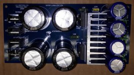
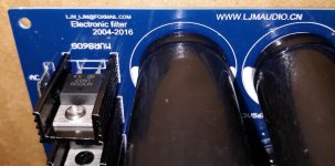
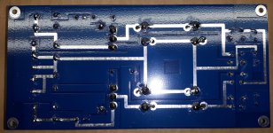
I recently bought an LJM Power Supply Filter (Capacitance Multiplier).
Is this a genuine LJM product? Or is it a fake? Are the capacitors real or are they fake? Especially the Nichicon KG 6800 uF 63V?
do u have sch for this?
No, I don't have a schematic.
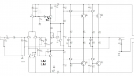
But it is very simple. The most basic capacitance multiplier consisting only of a Darlington, one resistor and one capacitor. Only a TIP142 with a 10k resistor to the base from the input filter caps and then one of the smaller electrolytic caps from base to ground.
Then the other smaller electrolytic cap is from emitter to ground on the output.
The negative side is the same except for polarities (uses TIP147).
The TIP142/TIP147 shorted twice and then I stopped trying to use it. I would look for a more rugged regulator design with some protection instead of this.
Well if you momentarily exceed the SOA the TIP142/TIP147 fail instantly in my experience with this board. (Twice.)
One suggestion was that I put a string of diodes from collector to emitter to protect the pass transistor if it comes out of saturation. Such as three diodes (about 1.8V). Also a protection diode from base to collector (for discharge protection).
Then a resistor in the emitter can be used to turn on an over-current protection transistor that steals the current from the base of the pass transistor.
I would suggest looking for a commonly used and well regarded design. I don't have one to suggest. Instead I went to using two regulated (SMPS) supplies. That (SMPS) is a more controversial choice but the ones I am using are working fine for me.
Perhaps someone else can suggest a good (rugged) regulator or capacitance multiplier to use. It is just my suggestion not to use the most simplistic type without any protection.
I changed the standard 220uF/63V rail buffers with 820uF/63V Panasonic Low ESR ones ( RS 571521 ) they fit on the board and this is audible as a tighter Bass .The standard input caps were changed by Elna SilmicII 22uF/63V . At first I was disappointed by this mod , found the sound a bit dull , but after a couple of hours the sound opened up and after a week or so it sounded much better as the originals .I also added 10.000uF/63V capacitors to each rail at the PSU ( that's for 5 amps in my case , so 3300uF or 4700uF will do for 2 amps or you might trip the overcurrent protection on the Connex SMPS )
Cheers ,
Rens
Does the 22-33uF input cap on the LJM L15D RS2092 IRAUDAMP7S amp form any sort of high pass filter or does it just just act as a DC blocker? If it’s just a blocker (1-4.7uF should be sufficient?) wouldn’t it be better to put a polystyrene/polypropylene cap there and keep any electrolytic out of the signal path?
Thanks,
Pete
IMHO, the problems of electrolytic is at best exaggerated. If you have a no polarised cap them by all means use it but I really doubt you will hear any difference.
IMHO, the problems of electrolytic is at best exaggerated. If you have a no polarised cap them by all means use it but I really doubt you will hear any difference.
chienmort: you are entitled to your opinion but I know a good number of builders who would disagree as I also do. The argument gets even cloudier by those who would argue that nothing in the signal path is the best concept.
Respectfully, however, I really was hoping for an answer to my question 😉
Pete
Hi Pete ,
As the L15D has a low input impedance ( 3k3?) , the DC blocker cap will have an effect on the low frequency -3dB point . as I recall the 22uF cap gives about 15Hz.
A smaller value like you suggest will affect your bass response .
Cheers ,
Rens
As the L15D has a low input impedance ( 3k3?) , the DC blocker cap will have an effect on the low frequency -3dB point . as I recall the 22uF cap gives about 15Hz.
A smaller value like you suggest will affect your bass response .
Cheers ,
Rens
Hi Pete ,
As the L15D has a low input impedance ( 3k3?) , the DC blocker cap will have an effect on the low frequency -3dB point . as I recall the 22uF cap gives about 15Hz.
A smaller value like you suggest will affect your bass response .
Cheers ,
Rens
Thank you much Rens!
Pete
Sorry: second try
Hello
This is my LJM-Audio L20.5 Amplifier.
I let pictures speak first.
https://www.diyaudio.com/forums/att...aar/835638d1587311061-ljm-audio-l20-5-amp-jpg
https://www.diyaudio.com/forums/att...87311061-ljm-audio-l20-5-amp-innenansicht-jpg
https://www.diyaudio.com/forums/attachments/vendor-s-bazaar/835640d1587311061-ljm-audio-4-ohm-jpg
https://www.diyaudio.com/forums/attachments/vendor-s-bazaar/835641d1587311061-ljm-audio-8-ohm-jpg
https://www.diyaudio.com/forums/att...r/835642d1587311061-ljm-audio-vg-m2-l20-5-jpg
@LJM Congratulations, with this Amplifier board you didn't promise too much
This is by far the best Amplifier I've ever built.
Thank you very much for that
Michael


The funny thing is that LJM specifically states not to use an SMPS with this board.
It seems like it is working well for you, has it held up over time?
Anyone any idea why LJM would say not to use an SMPS?
Thank you,
David.
- Home
- Vendor's Bazaar
- LJM Audio