@totally analogue:
Your suggestions were the first things checked and have been rechecked each time I have returned to this problem. The input signals are present and correct. All solder joints are reflowed and all electrical connections good.
@electricboyo
The new motors measure 4.0 ohms and the old ones 17.5 ohms. I think this enough of a difference to explain the odd behaviour and subsequent circuit damage.
The two plugs can be interchanged by mistake so I marked them long ago with coloured felt pen to ensure I don't do this as the clamper starts before the tray and grinds its teeth as a result.
I'll get the DSO from work today (even though my enthusiasm is currently running low...) and go back a step to look at the motor controller inputs and reset signal/clock.
This has long since ceased to be about having a nice CD player that works and more about not being beaten by a product which once worked and now doesn't. I could modify the tray for manual operation and put some logic on the controller input to operate the clamper with its own switch but I would always be wondering 'what if'.
I inspected the mechanism thoroughly while it was removed to be sure I hadn't missed any unseen sensors or broken mechanical parts.
The guy who designed it seems to have taken a simplistic view mechanically by using a switch for each status and a motor for each operation but making it work electrically became more of a challenge.
This problem reminds me of designing digital circuits at college that resulted in 'race' problems causing instability.
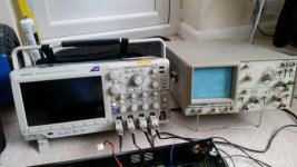
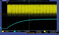
I have borrowed my works Tektronix 4 ch DSO for the weekeend (talk about taking work home...) so I can look at the tray/clamper operation in more detail as well as anything else.
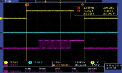
First is are the 3 motor control lines, M1 - yellow, M2 - blue and M3 - purple.
Pic 1: Tray closing, oscillating and opening with belts in place
First is are the 3 motor control lines, M1 - yellow, M2 - blue and M3 - purple.
Pic 1: Tray closing, oscillating and opening with belts in place
Attachments
I will take a look at the MCU reset/clock signals later and upload.
Any other suggestions welcome while I have a decent scope to hand.
Any other suggestions welcome while I have a decent scope to hand.
Does that scope have 3 channels or 4?
Actually 3 channels might be enough.
With belts installed look at these 3 signals:
1) Tray closed switch
2) M1, the on/off control input to the motor driver IC for the tray motor
3) M3, the direction control input to the motor driver IC
For now I’m ignoring the clamper because (to the best of my knowledge) it does nothing until the tray operation is completely finished.
-EB
MCU clock input frequency is specified in the service manual as 8.(something) MHz. It should be a totally clean stable square wave at standard logic levels for a 5V VCC supply rail.I will take a look at the MCU reset/clock signals later and upload.
Any other suggestions welcome while I have a decent scope to hand.
At power-up the clock must be stable before end of /RESET.
With that excellent DSO you should get some images of the eye pattern from the RF test point. I recently discovered that each CD has a slightly different eye pattern. The best one I’ve seen yet came from a (recent) commercially pressed disc. I also have an ancient Sony YEDS-18 test disc which doesn’t look as good. I’m going to try cleaning/polishing the disc surface. It’s badly scratched after 30 years of being on my workbench.
Another test I thought of:
Will this CD player initiate a “tray close” operation if you push in the tray just a small amount, rather than pressing the “open/close” button?
The reason for this is to use a completely different input to trigger the MCU to close the tray.
Yet another test is to close the tray with the remote control.
Each of these methods of getting the tray to close starts in a different section of the MCU firmware.
They may all produce the same behavior (oscillation of the tray). But there is always a chance of one of these acting differently.
-EB
Yes, that explains it. That big difference in DC resistance suggests the replacement motors the 6V version. But your CD player requires 12V motors.The new motors measure 4.0 ohms and the old ones 17.5 ohms. I think this enough of a difference to explain the odd behaviour and subsequent circuit damage.
If memory serves me I recall that most of these motors use for tray drive and other mechanical functions tended to be 6V. A 12V motor is somewhat rare. It’s a good thing that your original motors are still working.
-EB
The 300Mhz DSO is much nicer than my old analogue 20Mhz clunker from 30 years ago... although it's better than nothing. It is a 4 channel one and I made sure to grab all 4 probes before I left work today.
I'll get it hooked up and make some more measurements once I solder on some test points to connect to.
I'll get it hooked up and make some more measurements once I solder on some test points to connect to.
Attachments
Last edited:
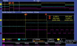
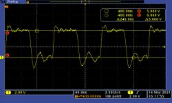
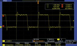
I've captured the clock signal at the MCU and I'm not sure it fits your description of totally clean stable square wave at standard logic levels... could do better I think! The rising and falling edges are well defined but the logic levels, particularly the low side is poor.
#EDIT: Frequency using the scope to measure is 8.453Mhz
The reset signal looks good and the clock is up and running in good time.
#EDIT: Frequency using the scope to measure is 8.453Mhz
The reset signal looks good and the clock is up and running in good time.
Attachments
Last edited:
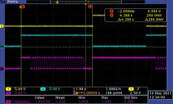
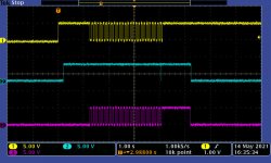
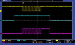
I've captured the tray closed switch (yellow) M1 (blue) and M3 (purple. Screenshot attached.
I contacted the eBay seller of the motors and explained what happened to my CD player drive circuit. They were very apologetic and refunded my money, which will go some way towards the faulty Pioneer SC-LX56 AVR I just snapped up on eBay!
I contacted the eBay seller of the motors and explained what happened to my CD player drive circuit. They were very apologetic and refunded my money, which will go some way towards the faulty Pioneer SC-LX56 AVR I just snapped up on eBay!
Attachments
I've traced the clock signal back to IC4 and IC3 and it seems to get noisier at the output of IC4. I added a couple of caps across the supply pins, 47nF and 10uF, which have cleaned it up a bit.
Although it looks better on the scope, it hasn't made any difference to the tray oscillation.
Although it looks better on the scope, it hasn't made any difference to the tray oscillation.
Attachments

Please let me know if I'm reading your images from the scope correctly?I've captured the tray closed switch (yellow) M1 (blue) and M3 (purple. Screenshot attached.
With tray belt installed:
The tray goes in, oscillates, and then eventually returns to the open position.
The clamper motor never runs.
This happens no matter how the "tray close" operation is initiated.
I see you made some cursor measurements. I will take a close look at those a bit later.
The clamper motor never runs.
This happens no matter how the "tray close" operation is initiated.
I see you made some cursor measurements. I will take a close look at those a bit later.
With tray belt removed:
It appears the clamper enters a similar oscillation pattern as the tray.
The clamper oscillation occurs when the clamper is nearly closed.
Eventually the clamper moves back to the open position
Then the tray motor runs for a while
Then the sequence of clamper close/oscillate/open happens again
And once again the tray motor runs for a while
And this repeats forever
The clamper oscillation occurs when the clamper is nearly closed.
Eventually the clamper moves back to the open position
Then the tray motor runs for a while
Then the sequence of clamper close/oscillate/open happens again
And once again the tray motor runs for a while
And this repeats forever
(With tray belt still removed) What is the clamper cycle like if the player is powered up in the following state:
The tray is already in the fully closed position
The clamper is in the open position
The clamper is in the open position
-EB
With the tray belt installed: tray operation is as you described
With the tray belt removed: clamper operation is also as you described.
With the tray belt removed: Power on with the tray closed - clamper closes, oscillates, opens, tray motor runs and the cycle repeats as before.
With the tray belt removed: clamper operation is also as you described.
With the tray belt removed: Power on with the tray closed - clamper closes, oscillates, opens, tray motor runs and the cycle repeats as before.
What happens if powered up in this state:
Belt removed.
Tray closed.
Clamper down (in clamped position).
EBTray closed.
Clamper down (in clamped position).
I will investigate this condition and post back.
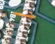
I currently have the main PCB removed to make the extra decoupling capacitors around IC4 a permanent fixture as they cleaned up the clock signal and the +5V rail at this point.
I also wanted to clean up and inspect the repairs to the motor controller chip as it was done late at night on Thursday night.
With the board out I noticed something that I hadn't before and can't explain. Pin 23 on the MCU has what looked like a track cut between it and pin 22. It is floating and not connected to pin 22 as shown on the schematic. Surely this can't be right?
Attachments
With the belt removed, tray closed and clamper down when the unit is powered up it stays in this state and will spin up the disc if there is one present.
I tried linking pin 23 to pin 22 as shown in the schematic but it made no difference to the problem.
The permanent capacitor mod to the area around IC4 has cleaned up the clock levels nicely but also made no difference to operation.
I tried linking pin 23 to pin 22 as shown in the schematic but it made no difference to the problem.
The permanent capacitor mod to the area around IC4 has cleaned up the clock levels nicely but also made no difference to operation.
Attachments
Does it look like something that was done at the factory?With the board out I noticed something that I hadn't before and can't explain. Pin 23 on the MCU has what looked like a track cut between it and pin 22. It is floating and not connected to pin 22 as shown on the schematic. Surely this can't be right?
Or something that was done later?
-EB
- Home
- Source & Line
- Digital Source
- Akai CD-93