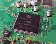
My first experience with dodgy DSP chips was nearly 5 years ago with a truck-sized Onkyo A/V receiver purchased on Craigslist.During that time I 'treated' myslf to a faulty Pioneer VSX-2021 to pass the time and discovered the problem with TI DSP chips.This model uses a D810K013BZKB4, which is a 256BGA device.
It was OK for a couple of months. Then the digital audio path began to drop out intermittently. The “direct” audio path was still OK.
Fortunately Onkyo offered free repairs to everyone!
It didn’t matter whether the unit was still “in-warranty.” It didn’t even matter if I was the original owner (I wasn’t). I filled out a form with the model & serial number. Onkyo sent me a big carton with prepaid shipping (nice!). The receiver was at Onkyo for about 3 weeks and came back with a brand-new digital/HDMI PC board in it. It has worked perfectly ever since.
Onkyo was one of the consumer electronic manufacturers who exerted a lot of pressure on TI. I think Onkyo handles customer support better than most. Since 1977 I’ve thought Onkyo was a reputable company. Back then I was in the home stereo retail business as both dealer & servicer. We sold tons of Onkyo products which often lasted a long long time.
-EB
I was a bit late to the game with the DSP chip problem as any support from manufacturers had long since stopped due to lack of parts. I contacted Pioneer about the VSX-2021 and they flatly denied any knowledge of the problem.
Removing BGAs is easy enough but fitting a new one is more of a challenge. I have an 858 heat gun too but the air flow needs to be reduced to stop it blowing the chip around. Liquid flux isn't great either as it bubbles and again the chip moves. I now use tacky flux in a syringe which is much better and helps hold the chip in place. I bought a reballing kit but although I have managed to physically place the new solder balls you need an IR oven to melt them so they're attached properly without moving.
With the larger QFP devices that have a ground tab underneath, I don't try and remove them in one go. I use a scalpel to gently cut all the legs close to the chip body and remove them with some flux and a fine solder tip. Then I heat the middle of the chip with the hot air gun and pry it away as the ground pad solder melts. That saves any pad or track damage.
Attachments
I also bought a faulty old truck sized Onkyo - the TX-NR807, as one of my first repair projects. Unfortunately it used the earlier 300Mhz D830K013BZKB3 chip, which is obsolete and can't be replaced with the later 400Mhz ones.
I reflowed it - luckily it works again and the service menu shows it has only 4500 hours logged on it. I decided not to sell it on as it will probably fail again at some point and it's impossible to say when. I'll probably wait til that happens and maybe have a go at reballing it with leaded balls.
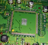
The QFP DSP in my photo is one I fitted this week to a VSX-922 and was sourced from a seller on eBay called e-best_trade. I've bought lots of semiconductors from him and all have been good quality at low prices. I inspected this one under a microscope and it isn't a fake or remarked device and works well now its fitted. The 'D' suffix chip can be used to replace the earlier 'B' or 'C' ones that suffer premature failure, although you're probably aware of that.
I reflowed it - luckily it works again and the service menu shows it has only 4500 hours logged on it. I decided not to sell it on as it will probably fail again at some point and it's impossible to say when. I'll probably wait til that happens and maybe have a go at reballing it with leaded balls.
The QFP DSP in my photo is one I fitted this week to a VSX-922 and was sourced from a seller on eBay called e-best_trade. I've bought lots of semiconductors from him and all have been good quality at low prices. I inspected this one under a microscope and it isn't a fake or remarked device and works well now its fitted. The 'D' suffix chip can be used to replace the earlier 'B' or 'C' ones that suffer premature failure, although you're probably aware of that.
Last edited:
I have purchased IC chips from e-best-trade (ebay vendor). I always had good results too.The QFP DSP in my photo is one I fitted this week to a VSX-922 and was sourced from a seller on eBay called e-best_trade.
In spite of all the negative chatter about Chinese ebay vendors I've bought hundreds of items from them without problems. And the prices are always right! My vetting process for ebay is to select vendors with >5,000 feedbacks & >99% positive. The very best have positive ratings approaching 99.7%. Then I buy a few inexpensive items to see how they look & work before placing larger orders.
Of course I also buy parts from US vendors like Digi-Key, Mouser, Adafruit, & Sparkfun. But they don't always have the items I need.
-EB
I've not had any problems with suppliers in China either but I agree with your careful process of scrutinising eBay feedback ratings before buying. I've found that applies to sellers anywhere in the world though.
I've also bought some good and well priced test equipment from China. Unitrend stuff is well built and good value. I have a multimeter, clamp meter and more recently an HDMI cable tester of theirs. That has proven very useful identifying suspect cables and shown that not all are created equal when it comes to screen and CEC connections.
I've also bought some good and well priced test equipment from China. Unitrend stuff is well built and good value. I have a multimeter, clamp meter and more recently an HDMI cable tester of theirs. That has proven very useful identifying suspect cables and shown that not all are created equal when it comes to screen and CEC connections.
After a bit of diversion I'm back to thinking about the Akai CD-73 tray drive.
Have you looked very carefully at the 3 driving signals that go from the MCU to the motor driver IC?
Do they always have "clean" logic levels and transitions?
These 3 signals should be either 0V or 5V at all times.
My concern is that perhaps the MCU isn't driving these outputs both "high" (5V) and "low" (0) as it should. The motor driver IC is kind of an "odd duck." It doesn't even receive a 5V supply. Rather it either has an internal 5V regulator or some other system for identifying low/high logic levels on its 3 input pins. It's important to confirm these 3 control signals for the motor driver aren't "floating around" at any voltage other than 0V or 5V.
Of the 3 control pins IN1 controls motor 1, IN2 controls motor 2, and IN3 selects the direction of rotation. Which motor (1 or 2) is the tray motor? Which motor is the clamper motor?
My expectation is that (for unknown reasons), The driver IC input pin for the tray motor is staying high (causing the motor to keep turning) but the direction pin is changing from forward to reverse.
I don't think the direction pin should be permitted to change state while either motor is running.
I'd like to view a "logic analyzer" display which shows these 3 input signals which go into the driver IC vs. time.
More questions:
What is the logic state of the direction pin while the tray is closing?
What is the logic state of the direction pin while the clamper is closing?
One might expect a short delay of 100usec up to perhaps a few ms between when the tray motor stops and the clamper motor starts.
One interesting fact is that eventually the clamper motor does get activated, but perhaps that only happens if you manually hold the tray in the closed position for several seconds until the oscillation behavior stops?
-EB
Let's pay some attention to how the MCU gets reset.
Although it doesn't happen often, really strange behavior can happen if an MCU doesn't always receive a proper reset signal at power-up.
The MCU \RESET pin is pin 28.
It is bypassed to ground with a 10uF capacitor (C12).
And tied to +5V with a 22K resistor (R7).
The MCU receives its 8.46MHz clock from the PLL.
I have no idea how long it takes for this clock signal to stabilize after power-up?
Is it possible that the low state of MCU \RESET isn't long enough?
I think the \RESET signal needs to stay low until after the 8.46MHz clock has totally stabilized.
Perhaps C12 should be larger? (22uF or 47uF)
There's more to the reset circuit: Back in the power supply section there are transistors TR17, TR18, and TR19 which appear to detect "power-up" and "power-down." It seems that the \RESET output should go low at the instant when mains power is interrupted.
-EB
I have looked at the motor driver control lines a few times although my scope is a fairly basic 30 year old 20Mhz 2 channel analogue one, so any detail is fairly limited. I plan to try and borrow a 300Mhz 4 channel DSO from work to help with these tests.
From what I've seen so far, the logic levels are good stable 0V and 5V levels with clean transitions. M1 and M2 are always stable levels (with the belts fitted) and it is M3 that goes into oscillation with the belt in place or when the clamper activates.
My observations so far, belt removed:
Tray Position M1 M2 M3
Open 0 0 0
Closing 1 0 0
Closed 1 0 1 * (oscillating 1-0 when belt fitted)
Opening 1 0 1
Clamp Position M1 M2 M3
Up 1 0 1
Down 0 1 0* (oscillating 1-0 when belt fitted)
Disc loaded 0 0 0
The clamper motor can only be persuaded to activate now by cycling the main power switch, which makes me think you may be onto something with the MCU reset circuitry. The 10uF capacitor was replaced with a new one when I replaced all the other electrolytics but I've not tried a different value in place of it.
If I can borrow the digital scope from work I can look again at the motor control lines together and also look at the MCU clock compared to the reset pin and see what's happening in more detail.
A quick bit of online research on MCU reset time constants gives a general rule of about 100mS as being enough for most applications. The Akai is 220mS, which should be enough time for the clock to have stabilised.
I've had the go ahead to borrow my Tektronix DSO from work over the weekend, so I will look at all the points discussed more closely to confirm what I'm seeing.
I've had the go ahead to borrow my Tektronix DSO from work over the weekend, so I will look at all the points discussed more closely to confirm what I'm seeing.
I think it will be OK to temporarily ground the /RESET pin of the MCU at any time to “force” a reset.
-EB
-EB
I'll try grounding the reset pin instead of cycling the power switch as a means of progressing the tray closing cycle to the clamping phase.
As I see it the main issue is with M1 failing to return to 0 when the “tray-closed” switch operates.From what I've seen so far, the logic levels are good stable 0V and 5V levels with clean transitions. M1 and M2 are always stable levels (with the belts fitted) and it is M3 that goes into oscillation with the belt in place or when the clamper activates.
My observations so far, belt removed:
Tray Position M1 M2 M3
Open 0 0 0
Closing 1 0 0
Closed 1 0 1 * (oscillating 1-0 when belt fitted)
Opening 1 0 1
Clamp Position M1 M2 M3
Up 1 0 1
Down 0 1 0* (oscillating 1-0 when belt fitted)
Disc loaded 0 0 0
The clamper motor can only be persuaded to activate now by cycling the main power switch, which makes me think you may be onto something with the MCU reset circuitry. The 10uF capacitor was replaced with a new one when I replaced all the other electrolytics but I've not tried a different value in place of it.
Instead M1 is staying high (1) for 4 seconds after “tray-closed.”
Some additional observation would help me fully understand M3 (direction control). Please confirm if this is accurate:
M1=1, M3=0 —> tray moves in closing direction
M1=1, M3=1 —> tray moves in opening direction
M1=1, M3=1 —> tray moves in opening direction
Next these questions need to be answered:
M2=1, M3=0 —> which direction does clamper move, up or down?
M2=1, M3=1 —> which direction does clamper move, up or down?
M2=1, M3=1 —> which direction does clamper move, up or down?
How feasible would it be to remove the clamper arm during testing to avoid the issue of jamming up the gear drive for the clamper when the tray is in the wrong position?
The exploded diagram shows a slide that moves back and forth to operate the clamper and it looks like the detector switches for the clamper are operated by this slide. If true then it might be OK to remove only the actual clamper arm while keeping the rest of the mechanism assembled. The goal is to be able to test everything without damaging the gear drive for the clamper.
Thinking about the root cause of the oscillation, it seems that reversing the tray motor immediately after tray-closed detection might be OK if the duration of this “reverse” was 4msec instead of 4 seconds. It’s like there is a timer algorithm inside the MCU which produces a much longer delay than it should be.
-EB
Testing has halted for the moment...
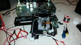
I removed the CD mech to gain better access to fit the new loading and clamp motors that arrived today and see how to release the clamper arm/disc assembly for testing purposes.
I put it back and powered it up but the geared slide pushed back too far locking the motor. There was a puff of smoke from the area of the controller chip so I hit the power switch pretty quick.
I need to investigate this before I reapply power but I suspect it may be the 8.2R resistor fried or the controller chip itself.
That 8.2 ohm resistor is a "flameproof fusible" resistor. They aren't necessarily "non-smoking" however. I expect it will now be an open circuit.
It must be replaced with another 8.2 ohm flameproof fusible resistor of the same wattage. That way it will continue to give protection to the circuitry.
In the worst case you might have destroyed the motor driver IC. But because the resistor died first, it's likely the motor driver IC survived. I believe the motor driver IC is still available, but there's no need to change it except if there is a fault with it after checking/replacing the 8.2 ohm resistor. If the driver IC did fail it will probably read shorted from VCC to ground.
Fortunately there's a 0% chance of this event damaging the MCU.
Hopefully no plastic gears or levers got broken in the process.
Getting the mechanical parts realigned can be a challenge. Over the years I learned to photograph everything prior to disassembly.
For "bringing up power" after getting things put back together I suggest placing an additional resistor (maybe 47 ohms) directly in series with the clamper motor. A resistor with enough ohms to give the motor just enough torque to rotate. Obviously 8.2 ohms is too small to do so. Also, the 8.2 ohm flameproof fusible resistor protects the driver IC and both motors, so it must always be replaced with an exact replacement. It's purpose is mainly to act as a fuse.
Therefore the safest thing to do is to add an additional resistor directly in series with the clamper motor to limit its fault current. I'd start with something around 47 ohms.
Another "old trick" for this is a 12V conventional incandescent automotive light bulb. A "tail light" bulb (not brake) is probably about the correct wattage for this purpose. This is the 12V version of the venerable "120V AC dim bulb tester" that everyone who restores antique radios uses. Incandescent light bulbs have a huge positive temperature coefficient. This makes them perfect for use as "current limiters."
Best of luck with this extremely challenging project!
-EB
Hats off to your perseverance! I was a tech at Akai in the eighties and worked there when the CD73 and CD93 came out. Beautiful machines just like the AT-93.
I don't bother with CD playback since a long time but I hope you manage to repair it. I read the thread and just found the CD93 toroid in my stock ;-)
I don't bother with CD playback since a long time but I hope you manage to repair it. I read the thread and just found the CD93 toroid in my stock ;-)
I replaced the 8R2 resistor, although it measured ok and had no signs of physical burning. I had a spare motor control chip and replaced this along with TR5 and D19 because the last attempt at powering up freed the clamper, which ran very slowly and then the tray opened at high speed... the opposite of what they should be doing!
The new components have made no difference to this condition and the tray opens and closes at the (incorrect) higher speed with oscillation and the clamper, when engaged, also oscillates at the (incorrect) slower speed. The 8R2 resistor is running very hot during this test as well. The mechanism is back together and correctly 'timed' as it only fits in one way.
I think I will call time on this project and accept that I've put enough effort and resources into trying to save a 30 year old CD player from the inevitable.
Andy, how frustrating. This might sound blindingly obvious but have you checked the draw closure signal is actually reaching the the microprocessor or whatever controls it? Could be a bad crimp on one of the ribbons connecting the drive to the main board or a poor solder joint.
With these small DC motors, their housings, mounting bolt pattern, shaft diameter (often 2mm), & shaft length can all look pretty much identical, but their armatures may be wound for different voltages and currents.Today's problems were caused by my replacement loading and clamp motors. Supposedly genuine parts, they were anything but!
Took the mech out for the second time today and refitted the old motors. Normal (dysfunctional) service has been resumed.
Some quick ways to ID whether two motors are electrically identical or not:
1) DC resistance. A variation of +/-20% is OK
2) Voltage vs. current under "no load" conditions over a range of voltages from 1V up to 12V (or whatever the rated voltage of the motor is).
3) No-load RPM vs. DC voltage. It helps to have one of those cheap "optical tachometer" guns.
4) Direction of rotation vs. the polarity marks on the input terminals
For these loading motors they are receiving a fixed voltage (12V) so you need a motor which actually runs at the correct speed when 12V is applied. The no-load RPM of a permanent magnet DC motor is directly related to the applied voltage. A 6V motor will rotate way too fast with 12V applied to it.
Curiously I have gotten away with ignoring motor voltage for disc player spindle motors.
Most of them are rated at roughly 4V, 6V, or 9V. This is often printed on the label as a spec called "D/V" which stands for "design voltage."
DVD/CD players made in the 2000's mainly have 9V spindle motors. But most CD-only spindle motors are 6V. I have a very large supply of 6V CD spindle motors on hand with several different shaft lengths. So I've often tried using a 6V spindle motor in a DVD player.
Did it work? Answer: perfectly.
Why? Because the motor is tightly controlled by the servo system. I actually didn't expect this type of substitution to work as well as it did.
What's good is that there was nothing wrong with your original motors. Perhaps tearing down the entire mechanism and inspecting all of it will be informative. Even if the original oscillation problem hasn't been fixed yet.
Is there any chance that permanent removal of the tray drive belt would work? You could attach a little tab to the front of the tray so it can be pulled out manually. The routine would be to manually push in the tray, and hopefully the clamper will settle down into the clamped position so that the disc will play. Then, to remove the disk you first press the open/close button to lift the clamper followed by manually pulling out the tray. ...just a thought for a work-around if you like everything else about this CD player.
-EB
Did you remove the grounding jumper from the CD-73/CD-93 selection pin on the MCU?I replaced the 8R2 resistor, although it measured ok and had no signs of physical burning. I had a spare motor control chip and replaced this along with TR5 and D19 because the last attempt at powering up freed the clamper, which ran very slowly and then the tray opened at high speed... the opposite of what they should be doing!
The new components have made no difference to this condition and the tray opens and closes at the (incorrect) higher speed with oscillation and the clamper, when engaged, also oscillates at the (incorrect) slower speed. The 8R2 resistor is running very hot during this test as well. The mechanism is back together and correctly 'timed' as it only fits in one way.
Pin open = CD-73, pin grounded = CD-93.
I recall the motor speeds changed when your tried CD-93 mode.
Also are the plugs on the cables for the 2 motors identical, as in: "this makes it possible to mix up tray vs. clamper when you plug the cables into the sockets on the PC board?"
This all goes to show how difficult repair/restoration can be when faced with a machine which is 27x more complex than it ever should have been in the first place!
-EB
- Home
- Source & Line
- Digital Source
- Akai CD-93