it was routine to transport the meters with the terminals shorted
Something i do with every loudspeaker box and driver(s) i ship so as to also minimize possibility of damage.
dave
This full-range driver technique described by Nelson Pass is about EQ, which is not what we are talking about here.
It is, but is it not really adjusting the impedance to cause that EQ? Rasmussun is doing the same to kill the bass resonances in the Elsinore, and the Nanosurus WAW has similar as optional.
dave
….ALL current driven systems have less thermal compression than ALL voltage driven systems?
Using the word ALL does not usually encomopass the set of devices we use in a given audio system given the huge number of compromises tha have to be made.
But as a generalization,VC temp is much, much less of an issue with current drive.
dave
Probably of more import is dealing with the much more common and growing segment of high Rout amplifiers that are still technically on the voltage source side of the chart, but getting close to the border, typically SETs, but we are seeing a growing number of SS amps where consideration of the effect of speaker impedance start imposing themselves (ie ACA, VFET, F2).
This is not a bad thing, it is just a different set of compromises and someone with greater understanding putting the system together.
dave
It is also a good way of making something that sounds different from other units, which is a requirement to get any penetration, whether commercially or in the diy market.
The ability to discern yourself from the 'competition' is critical, even when it is only with a good story!
Jan
Using the word ALL does not usually encomopass the set of devices we use in a given audio system given the huge number of compromises tha have to be made.
But as a generalization,VC temp is much, much less of an issue with current drive.
dave
It was a question in the context of whether you could do some measurements on the acoustic output of an amp+speaker system and determine whether it is a voltage driven or current driven system.
Jan
But ScottJ is right, acoustic distortion, with nearfield LF measurements to get the ambient noise floor down, this should be done.
A common thread of thot in Matt’s brain. "These things are easy”.
For those without anechoic chambers there is decidely some limitations to acoustic measurements.
dave
It was a question in the context of whether you could do some measurements on the acoustic output of an amp+speaker system and determine whether it is a voltage driven or current driven system.
Like measuring speakers for T/S parameters (Vs) i strongly suspect one other measure would be needed as reference. One probably needs a measure that shows how the speaker impedance affects the FR of the system.
One might be able to glimpse clues without, and as we explore the subject may be able to tease out some distinct characteristic that can be measured.
dave
I've a good mind to report that post as a personal attack, but I'm bigger than that 😉A common thread of thot in Matt’s brain. "These things are easy”.
For those without anechoic chambers there is decidely some limitations to acoustic measurements.
dave
Instead I will ask you to show me where I've said that. I've said on numerous occasions that drivers are very complicated and the only way to know what's happening is with acoustic measurements, something Joe has been reluctant to show.
For those without anechoic chambers there is decidely some limitations to acoustic measurements.
The lack of an anechoic chamber is no excuse: in case NF measurement won't do, LF measurements can still be done outside, in large halls etc.A.R. even used a flagpole on a parking lot. More work than a simple NF, but still quite doable.
The lack of an anechoic chamber is no excuse: in case NF measurement won't do, LF measurements can still be done outside, in large halls etc.A.R. even used a flagpole on a parking lot. More work than a simple NF, but still quite doable.
Correct me if I am wrong, but to my best of knowledge CLIO can derive T/S parameters from a free air impedance measurement of a woofer.
I have a question- will a tube OTL design like the Circlotron not also work very well? I am thinking of a pair of 6C33C tubes a Circlotron design.
Hello Baffles,
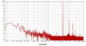
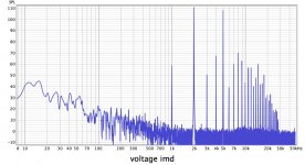
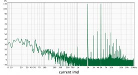
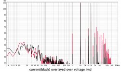
Would you be wiling to provide us with SPL plots in the regular format, with 5 dB/div, with some smoothing, to compare V and I drive for the BG 20 to make the comparison a bit easier? Even nicer would be if an overlay could be shown.
Would you be wiling to provide us with SPL plots in the regular format, with 5 dB/div, with some smoothing, to compare V and I drive for the BG 20 to make the comparison a bit easier? Even nicer would be if an overlay could be shown.
some measurements current and voltage drive visaton BG20 driver. acoustic output.
I used to have those Visaton drivers, pair. Thanks for sharing, yes it is the acoustic output.
Now try to put a small inductor in series and see if you do not see a reduction in distortion with voltage drive, something that gets closer to current drive. You may have to vary the value of the inductor till you get a value that looks good and has not affect on above 5KHz. The BG20 may suit a two-way better that way, but if you see an improvement, note that the reduction is greater than the frequency attenuation of a 1st order filter. Try it if you have the time.
But thanks again - there are things falling into place and we are better at understanding what is going on and how it works. The driver is modulating the current of the amplifier which in turn is affecting the force-factor (BL) of the driver. When the voice coil moves, the impedance of the driver changes. It is worst when a low frequency signal (excursion) coincides with things happening in the midrange. I am not the only one who has looked at this.
Now try to put a small inductor in series and see if you do not see a reduction in distortion with voltage drive, something that gets closer to current drive. You may have to vary the value of the inductor till you get a value that looks good and has not affect on above 5KHz.
So basically what you are trying to say here is that with this inductor the driver will work towards voltage drive at low frequencies and towards current drive at high frequencies? If that is the idea than i understand it and don't have time to test it 🙂 if you meant something else correct me. I have adjustible corner frequency in amp for transitioning from voltage to current drive so don't need an inductor test
So basically what you are trying to say here is that with this inductor the driver will work towards voltage drive at low frequencies and towards current drive at high frequencies? If that is the idea than i understand it and don't have time to test it 🙂 if you meant something else...
Alas, it's more complicated than that. Real Old School says that the damping at LF is entirely defined by the alignment. The whole thing about 'damping factor' is not compatible with that view. But if you adjust the volume of a box and aim to be -3dB at the box frequency, say 50Hz, then you will be -12dB at 25Hz. This is a classic 2nd Order Sealed Butterworth alignment and the fact is you get the damping of a 2nd Order Sealed Butterworth alignment, simple as that. Change it to a Bessel alignment, then you have a more damped alignment etc.
The rest, as they say, is marketing.
But it is actually worse than that, and here the trolls might come after me (I am evidently some kind of heretic), it is doubtful that there really is such a thing as voltage drive. There, I said it! The DC resistance of the voice and the output impedance of the amplifier is put into series and become a single value. The amplifier sees only the single value of the two added together. It does not see its own output impedance unless the output is shortened, and that is not a good idea. Yet the folly continues.
Hello everybody .
in my mind I imagine a transconductance amplifier as a fixed voltage generator whose variable output resistance is inversely proportional to the voltage signal applied to the input. minimum input signal maximum output resistance, maximum input signal minimum output resistance.
if we bi-amplification and active line crossover we can drive every single speaker with an amplifier dedicated to it.
in frequency, as a result, we get a variable linear resistance (amp) in series with an impedance that behaves as it prefers (speaker) and nothing else.
If this is the case, between speaker and amplifier we have a signal to exploit and send back to the amp input to achieve movement feedback and have damping with distortion reduction.
did I write everything right so far?.
to accomplish the same thing in the simplest way with a voltage amplifier that has a very low output resistance, we need to apply a resistor in series to the speaker.
What do you think ?.
- Home
- Amplifiers
- Chip Amps
- Joe Rasmussen "Trans-Amp" - 40 Watt Transconductance "Current Amplifier"


