Edit: overpost.. @Joe
Silly business.. We black-boxify a speaker for a crossover simulator, what goes in, what comes out. The same kind of "parameter consolidation" goes on in normal conversation, such as post #551.
Add functionality, define the box.
Silly business.. We black-boxify a speaker for a crossover simulator, what goes in, what comes out. The same kind of "parameter consolidation" goes on in normal conversation, such as post #551.
Add functionality, define the box.
In most speakers you find that the speaker impedance and acoustic cone gain are matched so that the speaker can have a reasonably flat response. This gives speaker designers greater flexibility in the type of cone they can use. They can select a good performing cone and tweak the motor geometry to get flat response.
With current drive you are much more limited in the design you can use if you want to make a speaker with flat response, which a speaker must have to be useful in a variety of implementations.
With current drive your speaker response is the pure acoustic cone gain. For voltage drive speakers with a high voicecoil inductance, the treble will be boosted and this limits your SNR unless your amp is designed specifically for that speaker. Maybe not so much of an issue nowadays with fairly quiet amps.
Any crossover design which allows the speaker EMF and MMF to affect the current through the voicecoil is discarding the benefits of current drive, so zobels are not the answer.
F=B*U/R*L.
Why is it Joe, that an R is something else wether it is in a field or not. If you made your field taller in your example, would the 2 Rs go away?
//
Why is it Joe, that an R is something else wether it is in a field or not. If you made your field taller in your example, would the 2 Rs go away?
//
Would a speaker be the same if a near zero resistance voice coil (of the same mass and size) was used, and the resistance was added externally? (I meant to ask this yesterday)
Zobels are for the benefit of the amplifier and/or crossover, they don't effect the behaviour of the individual drivers.
Zobels don't affect performance in voltage drive, if you are using a good amplifier. In current drive they reduce the reduction in distortion you can get, although maybe not in every case.
No. The eddy currents in the pole piece and pole plate shape the impedance curve which shapes the frequency response in voltage drive.
Would a speaker be the same if a near zero resistance voice coil (of the same mass and size) was used, and the resistance was added externally? (I meant to ask this yesterday)
No. The eddy currents in the pole piece and pole plate shape the impedance curve which shapes the frequency response in voltage drive.
Isn't that more to do with the amplifier/zobel interaction than what's going on after the zobel?
An ideal amplifier is linear, and an ideal zobel is linear. There is no interaction between them that can cause distortion.
In current drive, the zobel shunts the amplifier's output impedance, so the speaker sees more of a voltage source than a current source.
It is true that at any other frequency than Fs, the coil impedance >> the electromechanical impedance, so the speaker is electrodynamically current driven. But the coil impedance is nonlinear due to hysteresis, the dynamic magnetization of the motor assembly and it's varying position within the motor, so this is a bad thing, not a good thing, and it is actually what we are trying to fix by using current drive.
Last edited:
That makes sense to me. KT do you have an idea of the ratio of the electrodynamic impedance to the voice coil resistance (which I guess is like 5 or 6 ohm in most cases for an 8 ohms driver)?
Jan
Jan
My own experience with a composite voltage/current amplifier is that the sound is much cleaner, and the amp is less influenced by the driver.
Would a speaker be the same if a near zero resistance voice coil (of the same mass and size) was used, and the resistance was added externally? (I meant to ask this yesterday)
Affirmative!
Bring on super-cooled conductors and wire! 😎
This is a quote from August 1947 Wireless-World:
"In your April issue, D. T. N. Williamson refers to electromagnetic damping of a baffle-loaded loudspeaker, through low output resistance of the amplifier, as being important.... I used to agree... but my belief was much shaken by the following argument.
"If a loudspeaker can be represented by an equivalent circuit consisting of a resistance in series with an 'ideal' loudspeaker of 100 per cent efficiency, then the damping must be applied across the input terminals.
"In this case, even if the amplifier output resistance is zero, the damping is limited by the series resistance which, for 5 per cent efficiency, would be twenty times the resistance of the ideal loudspeaker. This extreme simplification, of course, leaves out the reactive components of the speaker impedance, but the argument still holds qualitatively.
"Can any reader of Wireless World point out any error in this argument? If it is true, there is very little gained by attempting to achieve excessively low output resistances." F. Langford-Smith
His nose was right. He instinctively knew that the series resistance was only a single value. Later in 1960 Thiele-Small confirmed this mathematically and Richard Small put it to me directly in person. He gave me a series of tables of how to manipulate alignments (and hence the real damping) by adding series resistance values and combining with different volumes. I am speaking of sealed boxes here. In the formulas, there was only a single Re and it was the total loop resistance.
Conclusion: Whether it is the output impedance, the cable resistance, the likely inductor DCR, and the DCR Re of the driver, the whole length is both inside and outside that gap, has to be calculated as a single value.
I am glad you asked the right question, I wish others could see that. Oh yeah, actually a LOT of those I have spoken to had no problem understanding this at all. How about that? 😀
Cheers, Joe
That makes sense to me. KT do you have an idea of the ratio of the electrodynamic impedance to the voice coil resistance (which I guess is like 5 or 6 ohm in most cases for an 8 ohms driver)?
Jan
On the impedance chart, look at Fs and extend the left and right sides down at a 6db/oct slope below Re. Cone modes may create smaller peaks that approach Re which can be seen as disturbances in the impedance curve in some speakers.
The electrodynamic impedance falls above Fs until the cone becomes compliant and/or the wavelength of sound in the cone becomes smaller than it's diameter.
The electrodynamic impedance is proportional to the mechanical compliance of the cone which is highest at Fs. Magnetomotive force (MMF) is proportional to velocity.
"If a loudspeaker can be represented by an equivalent circuit consisting of a resistance in series with an 'ideal' loudspeaker of 100 per cent efficiency, then the damping must be applied across the input terminals.
"In this case, even if the amplifier output resistance is zero, the damping is limited by the series resistance which, for 5 per cent efficiency, would be twenty times the resistance of the ideal loudspeaker. This extreme simplification, of course, leaves out the reactive components of the speaker impedance, but the argument still holds qualitatively.
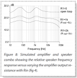
Joe, I hear what you say, but how does that figure with the known phenomenon that with higher amp output Z, the speaker starts to deviate from flat due to decreasing damping.
See attached graph, where the speaker coloration due to lack of damping increases with higher amp Zout.
Jan
Attachments
Joe, I hear what you say, but how does that figure with the known phenomenon that with higher amp output Z, the speaker starts to deviate from flat due to decreasing damping.
See attached graph, where the speaker coloration due to lack of damping increases with higher amp Zout.
Jan
I could never quite understand the way damping is explained in terms of impedance. My understanding of damping is the nature to resist external interference. With this understanding, my measurements using a MyRef amp was much more better than traditional voltage designs. Not sure about this one in this thread though.
But to me, resistance to driver backemf gives a cleaner and transparant sound, then it is a better design interface.
Damping is usually thought of in terms of a resonator which is critically damped with a resistance equal to it's characteristic impedance Zo=sqrt(L/C). Mechanical resonators can be thought of the same way.
Resonators are also good antennas, so yes there is an aspect of interference.
For a parallel resonator, which is what the speaker's electrodynamic impedance is, a parallel resistance increases damping whereas a series resistance limits it.
Most speakers are designed so that they can never be overdamped due to what is driving the speaker, so the coil resistance is about equal to the Zo of the electrodynamic resonance at Fs.
I fail to see what makes this special or exclusive knowledge.
Bring on super-cooled conductors and wire! 😎
...................[ WW abstract, cut!]...................
Conclusion: Whether it is the output impedance, the cable resistance, the likely inductor DCR, and the DCR Re of the driver, the whole length is both inside and outside that gap, has to be calculated as a single value.
Oh well, as Re changes with temperature
And program material cannot be calculated, must not enter the equation.
We're left alone with that hot magnets!
In the past when we were still using coil panel meters, it was routine to transport the meters with the terminals shorted.
This damped the meter movement and prevented damage during transport.
If you didn't short it, movement often violently slammed the meter needle in one of the stop positions with a chance of damage.
Such a meter is a coil in a magnetic field, the same as a speaker driver. That shorting is exactly the same as damping a speaker with a voltage source.
D’Arsonval Movement - Inst Tools
Jan
Last edited:
And if you are goig MFB as I do.. I also benefits the fact that the phase margin is increasing with CFB. Because of the higher phase margin I can crank up the gain in the MFB loop and reduce the distortion even further.
22dB so far but i´m trying to reach 25 dB.
This is impossible without current feedback i would say.
22dB so far but i´m trying to reach 25 dB.
This is impossible without current feedback i would say.
- Home
- Amplifiers
- Chip Amps
- Joe Rasmussen "Trans-Amp" - 40 Watt Transconductance "Current Amplifier"