Voltage to current ratio is also measurable. Current across the sense resistor is measurable. Voltage across the sense resistor is measurable. Via the feedback network, the amplifier maintains a constant voltage across the sense resistor. This also means the amplifier maintains a constant current across the sense resistor. Once an additional unknown or variable load is placed between the opamp output and the sense resistor, the only constant at the opamp output is the output current, because the same amount of current is required to maintain the desired voltage across the sense resistor, while the voltage at the output will adjust to accommodate that current. So current output amplifier seems like a quite accurate description of what's actually happening. And accurate descriptions are relevant because we're speaking in language to describe things. If you still feel the only way to describe it is as a variable voltage output amplifier, i guess that's fine, but it's not very informative.
Last edited by a moderator:
Voltage to current ratio is also measurable. Current across the sense resistor is measurable. Voltage across the sense resistor is measurable. Via the feedback network, the amplifier maintains a constant voltage across the sense resistor. This also means the amplifier maintains a constant current across the sense resistor. Once an additional unknown or variable load is placed between the opamp output and the sense resistor, the only constant at the opamp output is the output current, because the same amount of current is required to maintain the desired voltage across the sense resistor, while the voltage at the output will adjust to accommodate that current. So current output amplifier seems like a quite accurate description of what's actually happening. And accurate descriptions are relevant because we're speaking in language to describe things. If you still feel the only way to describe it is as a variable voltage output amplifier, i guess that's fine, but it's not very informative.
Hello All,
last thing first; who said the only way to describe it is as a variable voltage output amplifier. A bit of confabulation?
Keep in mind that a transconductance amplifier is a differential voltage input amplifier, the difference between the two input voltages is what is amplified. The voltage across the sensing resistor is only part of the calculation. Sure the output voltage / current will increase if the voltage across the sensing resistor goes down. However the output voltage / current will not hold constant making most of your statements in the above post false.
If it helps; visualize the voltage divider formed by the driver load and sensing resistor. The sensing resistor is a stable resistance. The impedance of the driver is all over the map variable.
Put away that "accurate" word and test your assumptions.
Thanks DT
Last edited:
Hello Joe,
This transconductance amplifier would it work as a headphone amplifier for 300ohm headphones?
This transconductance amplifier would it work as a headphone amplifier for 300ohm headphones?
I am not Joe, but i see small issue...there is no common ground. You have to modify your headphones.
Yes. a good question. But as adason and Baffless points out, you can't use a common ground. But if you rewire the headphones so that they don't have a common ground, that should work. But are you willing/able to do that with the headphones you have in mind?
Yes, a common ground is possible. It's just the feedback is a bit complicated for a defined output impedance. A current source is not so complicated and is called a "Howland" current source. https://circuitcellar.com/resources/quickbits/howland-current-source/
I posted this before, to program the output impedance to say, 8 Ohms. The non-inverting circuit is a bit different from the inverting circuit. Both require an input buffer because the feedback requires a ~zero impedance source. Let me see if I can find the simulation and feedback resistor spread sheet:
CSV file:
A,R,Z,N,P,Na,Pa,Nb,Pb
23.5,0.39,4,=1+(A2-1)B2/C2,=((A2-1)*B2+C2)/(C2-B2),10000,10000,=F2(D2-1),=G2*(E2-1)
,,,,,,,,
inverting,,,=1+A2*B2/C2,=(A2*B2+C2)/(C2-B2),10000,10000,=F4*(D4-1),=G4*(E4-1)
Attachments
Oops, wrong png file:
This is just two 4 Ohm outputs. It was made to address the bridging issue, but you just need the non-inverting part. You can copy the text into a CSV file and adjust the gain, sense resistor, output impedance and one part of each feedback divider (Na,Pa).
This is just two 4 Ohm outputs. It was made to address the bridging issue, but you just need the non-inverting part. You can copy the text into a CSV file and adjust the gain, sense resistor, output impedance and one part of each feedback divider (Na,Pa).
Attachments
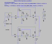
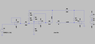
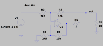
The constant current "Howland" circuit is simple because both feedback dividers are the same. The Voltage gain is the product of the feedback divider ratio and the load/sense resistor ratio. Here 4x10=40, 10k/2k5 * 10/1. (The amp still has the same clipping voltage as a voltage output.) The input source impedance has to be (near) zero, ie buffered. There is a potential issue with chip-amps that have a limited common mode input voltage.
Attachments
Last edited:
Hello Joe,
This transconductance amplifier would it work as a headphone amplifier for 300ohm headphones?
Let's not forget this was the original question. The answer was given and it was no common ground and that the drivers in left and right can float right back to left and right of the amplifier in question, otherwise the answer is no for that particular amplifier.
Sure, there are ways to do things, there usually is if we want to go back to scratch and create a new amplifier. But only 'wattsman' can answer that question.
Having said that, current driving 300 Ohm Sennheiser headphones, that's an interesting proposition. I have a pair of HD650 (they have been around for many years and still around) and they are 300 Ohm. You can buy the separate left and right connected and make your own wiring/cable back to the amplifier I have got.
Recently I tweaked the circuit and was able to get 1000 Ohm on the output.
So to 'wattmans' which headphones do you have? We might have the answer that suit this particular amplifier.
I might try measuring the impedance (a graph) and see what it looks like.
Last edited:
Hello Joe ,
I have the HD600 which are very close to HD650.
It would be great to see your graph And I could make up a cable also that would work .
Best regards
FDB
I have the HD600 which are very close to HD650.
It would be great to see your graph And I could make up a cable also that would work .
Best regards
FDB
Good question. Need to see whether the proponents have EQed it back to flat.What is the experience concerning sound with headphones married to transconductance amps?
When I get those connectors, yes I ordered them on AliExpress, it will be easy to measure the impedance, it should be interesting. Will EQ be required? Yep, we need to see. Re HD600 vs HD650, I have heard some prefer HD600, but I managed to get HD650 around 1/3rd of their current retail price.

Didn’t test current drive with headphones, but it should be good. From electrodynamic fulrange visaton BG20 speaker tests i can say that equalizing to same measured response probably not enough. Maybe needed to lower high frequencies more for the same tone perception. Equalized exactly for the same (sine sweep measurement)current drive sounds more brighter. Feels like more highs present compared to voltage. Distortions are lower for the current, so how to explain i don’t know and did look for answers. I switch between current or voltage drives on the fly from my phone so comparison is pretty accurate.Good question. Need to see whether the proponents have EQed it back to flat.
I did measure both channels of my Sennheiser HD650 headphones:

In my opinion you could use a current source to drive these headphones. But there are a couple of things to keep in mind.
1. Yes, there will be an emphasis centered around 100Hz. I am not saying that it won't be audible, it will. But it may still be acceptable and some might even like it that way.
2. The measurement goes up to 40KHz plus and the impedance is almost be flat to 10KHz and so will the response. Here I suspect it will be much less audible as a difference.
3. And this one is easy to overlook: To get real current drive with this high an impedance, the source impedance needs to be huge. The minimum requirement that bot Esa and I agreed upon is 5:1 and that means a source impedance of 1500 Ohm. If the impedance is lower than that, then the boost discussed in points 1. and 2. will be much less.
Any other thoughts?
This doesn't appear to be relevant.. it's as if you're only looking at 'current source effect' based on the standard definition of 'significant' being an order of magnitude greater impedance.The minimum requirement that bot Esa and I agreed upon is 5:1
However is there really a 'current source effect', or are we losing sight of the real issue? Surely the relevant factor ought to be the audibility of distortion. This would tend to make the requirements different in each case.
Last edited:
However is there really a 'current source effect'
That ratio was discussed around ten-twelve years ago, Esa then pointed out in his 2016 paper which included distortion measurements (none were in his book) and that an equal value still gave benefits. So that is 2:1 and I seem to recall that the benefit distortion wise would be 6dB improvement.
So add 8R to an 8 Ohm speaker and you would have what you called a 'current source effect.'
In some discussions this has been called 'resistor drive' and of course if you have a 100W amplifier to become 25W nominally.
Surely the relevant factor ought to be the audibility of distortion. This would tend to make the requirements different in each case.
Yes indeed, I agree with you. It's all about distortion. Always is.
I am intensely interested in the mechanism (how this distortion is formed) involved. Some will say that this reduces the distortion of the driver (here the headphones). I think there is more involved.
Just like i said, you tend to disagree a lot.
Would you give an example? I am not a disagreeable person.
- Home
- Amplifiers
- Chip Amps
- Joe Rasmussen "Trans-Amp" - 40 Watt Transconductance "Current Amplifier"