... I will have to use the normal Schurter ones that are rated for 10A...
You don't have to. Make a little board to block off the cutout and hard wire a suitable cable, like those for electric stoves. Problem solved, amp side. Now where do you plug it into? The US wall plug (NEMA 5-15) is only rated for... 15A.
Of course, with a delayed turn-on and on the practical side, I don't see a problem. But the legal side may be an issue.
Again, that's everyone for all your advise, I ordered all parts finally and I should start assembling this week, still have to figure out the whole Inrush Current situation and see what works best.
Something not a show stopper but that would be nice (cleaner) is, I've been trying to create a bigger OS PCB from ZM's Gerbers to include all 12 pairs (or 11) that Pico's Ultimate Chassis can hold but for some reason Eagle 6.7 keeps saying there are issues while opening the files 🙁
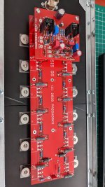
Today in order to fit 2 of the 6 Pair OS boards I have to put one on top of the other since they both don't fit as they are.
Has anyone successfully open the Gerbers and made some changes?
you can't work Gerbers in Eagle
here it is, do what you want - Eagle files for 8deep
Sorry ZM, silly me, I have these files already and that's what I meant not Gerber files. I'll keep trying 😱
nope Bubba, I'm not making 12deep
🙂
That's fine ZM, you've been more than generous already, I was just wondering if someone had seen those errors I'm getting, most likely its just me having to learn.
...
Has anyone successfully open the Gerbers and made some changes?
What I did was: open ZM's files in Eagle, save them in a previous version format (V5?), then import them into KiCad. Not nice, but it works.
Because I wanted to implement quite a few changes, I finally ended up starting from scratch in KiCad that I've used before. But if you ask me, its user interface is a tragedy.
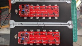
Some progress, this is one of two build sides.
View attachment 950200
Not wired up as yet, getting there.
Lord knows why the picture is sidewards on, I rotated it and everything...grr!
nice looking chiily
don't fret about pic orientation, I can always rotate my head to see it
just take care when you finish your amp, to orient it properly on the floor
🙂
Attached is a parts list and my build notes. I used a PSU board designed by Jeff Young. 22,000mfd per rail. 2, 300VA-25 V transformers from Antek.
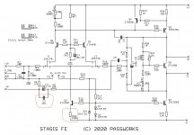
I was looking through your BOM and I noticed that you have R10 at 10k, where as the FE cct has R10 as 150R. Did I miss something?
And bugger, I have installed a 150nF in C2 rather than a 15nF. my eyes must be going 🙂 I'm not using the balanced input and C2 just looks to be a bypass cap, so I can ignore the wrong value I've fitted?

Ta.
A matching pair on 4U, 400mm heatsinks.
Very Nice, I hope I have time to start populating mine this weekend!
- Home
- Amplifiers
- Pass Labs
- New Stasis front end


