not sure that 1mH is enough
in some cases ( remember that amp is more AB Class) with small inductance , filter can go in resonance
in some cases ( remember that amp is more AB Class) with small inductance , filter can go in resonance
Last edited:
dc rail already went down from 57 to 40v after the filter on 1ohm load, increased inductance will also increase esr and dc rails would sag further..
well, 1 Ohm is hard load, I'm not expecting your amp behaving as that
if yes, you're in trouble ...... I mean your wallet is in trouble
1R means 40+ Amperes of current
which means - Yikes!, time for Fire Brigade
but, no biggie - that's just simulation, and that's the way of learning
🙂
if yes, you're in trouble ...... I mean your wallet is in trouble
1R means 40+ Amperes of current
which means - Yikes!, time for Fire Brigade
but, no biggie - that's just simulation, and that's the way of learning
🙂
I base my working on Murphy's Law: Anything that can go wrong will go wrong!
with 5 channels loaded to 4 ohm loads, do you think the 910va xformer will suffice? in HT duty the load is mostly dynamic..
with 5 channels loaded to 4 ohm loads, do you think the 910va xformer will suffice? in HT duty the load is mostly dynamic..
Look at what I received today, finally got them on the second try, I’d say it was well worth the wait!!
Now I’ll start putting the BOM together.


Now I’ll start putting the BOM together.

I've settled on a 2x24, 750VA transformer, which feels about right for this amp. I don't want too much voltage in to my 57s 🙂
Does that seem a reasonable choice?
Ta.
Does that seem a reasonable choice?
Ta.
OK, I'm about to order the FE and OS parts but I still have a few noob questions:
I'm thinking 2 * 6 Deep OS PBs per channel so 11 Pairs per channel, 80 VDC Rails?
1. I know I have to change ZTX450 and ZTX550, do I need to change Electrolytic Caps C3, C4, C7 for a higher voltage Rating?
2. Is Mouser Part# 527-NK202C2R5 a good option for R24 2K Thermistor?
3. KSA1220 is Out of Stock, any other good pair to substitute 2SA1381 and 2SC3503?
4. Has anybody tested any Capacitor in C5?
Any suggestions on a good Power Supply Design 😀 ?
Thanks in Advance!
80Vdc rails ?
no need to change any cap voltage
need to recalc R8, R9 , to keep JFet voltage at bay ...... say no more than 15-20V (ZM Chicken Book sez so); no need for more than 1-1.5mA through these res.
trannies - account on both voltage and dissipation; more than 200mW per tiny TO-92-like, use slip-on heatsink
same applies to Q5,Q7 - check temp. when done and- if you can't keep fingers on them , increase length of h'sinks
2. seems OK
3. eek, next question
4. Pa sez - do not; when done , observe squares; then you'll know
really - 80V ....... better wait Big Boy to chime in, to give few advices ........ he's the one who knows that OS
all part names ref. to schmtc of my Picolo pcb

I might have some A1220 that you could have, but it seems like there were q couple alternatives noted very early in thread.
80Vdc rails ?
all part names ref. to schmtc of my Picolo pcb
I might have some A1220 that you could have, but it seems like there were q couple alternatives noted very early in thread.
Thank ZM and hirscwi!!
I'm doing my homework on those changes, I'm sure I'll have more questions soon, you guys rock!

TH1 is it possible to use 1K instead of 2K .
Possible, but 2k gives the best tracking for the original design. Go ahead and try it.
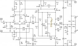
Ok, I’ve been running some simulations and looks like for 80V rails I need to change R8 to 20k, R9 to 6k to keep JFET voltage around 18V, sounds right?
Also simulator shows R13 going PoP, having to dissipate over 2 Watts, so looks like that one needs to be changed to 30k to stay under 250mW or 20k and use one of the small .5W resistors. Does that change have any adverse effect?
According to the simulator the FE has 0.009% THD @ 1kHz - 1 Vpp at input.
Ok, I’ve been running some simulations and looks like for 80V rails I need to change R8 to 20k, R9 to 6k to keep JFET voltage around 18V, sounds right?
Also simulator shows R13 going PoP, having to dissipate over 2 Watts, so looks like that one needs to be changed to 30k to stay under 250mW or 20k and use one of the small .5W resistors. Does that change have any adverse effect?
According to the simulator the FE has 0.009% THD @ 1kHz - 1 Vpp at input.
80V rails
R8 68K, R9 12K ; normal peanuts 600mW will do
R13, increase to 9K1; dissipation is then 550mW - you can buy 1W MOX in 0207 size, just elevate it from pcbm some 5mm or so
or even better - put two 4K3 (600mW peanuts) series in R13 position - vertically, connect them horizontally in between
again, everything ref. to small FE pcb
- Home
- Amplifiers
- Pass Labs
- New Stasis front end