OK, I'm about to order the FE and OS parts but I still have a few noob questions:
I'm thinking 2 * 6 Deep OS PBs per channel so 11 Pairs per channel, 80 VDC Rails?
1. I know I have to change ZTX450 and ZTX550, do I need to change Electrolytic Caps C3, C4, C7 for a higher voltage Rating?
2. Is Mouser Part# 527-NK202C2R5 a good option for R24 2K Thermistor?
I bought a pair of these Blocked But then I bought the output devices from Digikey too (2SA1695/2SC4468), so saved on the postage 🙂
3. KSA1220 is Out of Stock, any other good pair to substitute 2SA1381 and 2SC3503?
I bought KSA1220/KSA2690s from Digikey too, but out of stock now 🙁
4. Has anybody tested any Capacitor in C5?
Any suggestions on a good Power Supply Design 😀 ?
Thanks in Advance!
Thank you all for your replies and help so far, I’m not even close to done (not even started), so I’ll have to keep bugging ya’ll...
As I try to design the Welder Power Supply I’ve been looking at Antek Toroidals and I found Papa’s comment (picture) in a post, I guess that’s enough for a blessing?
Is there any other brand that won’t break the bank, fairly priced like them that you can suggest?

As I try to design the Welder Power Supply I’ve been looking at Antek Toroidals and I found Papa’s comment (picture) in a post, I guess that’s enough for a blessing?
Is there any other brand that won’t break the bank, fairly priced like them that you can suggest?
Last edited:
2500VA Transformer
I've been trying to design the power supply and I've been looking for options, I started trying to put 2 X 1000VA toroidals but then I ran into cabinet space issues because 2 of these plus at least 4 Capacitor Cans will be hard to fit in Pico's Cabinet, so because of that I changed to 1 bigger toroidal, AnTek has a 1500VA one that may work well but then I found this 2500VA one from TRIAD Item # VPT100-25000, Toroidal Mount World Series™ Power Transformers On Triad Magnetics and I got all excited thinking about the thermistors I'll need for the inrush current and how I wanted to design the bridge rectifier configuration etc. BUT when I was doing that I noticed a Note that says "Primary and secondary windings are designed to be connected in series or parallel. Windings are not intended to be used independently." and my ignorance is wondering why would that be?
Does that mean that I'm limited to 1 single bridge rectifier rather than 1 per rail for better performance?
If that's the case I guess it'd be better to use a Discrete Diode Bride Design like used in the Universal PSU v3.0?
just ignore that remark
it can be that they wound them bifillary, with note being sure that windings will never be put on some crazy different potentials
xformer is xformer - it is either good or bad, but never some special unknown animal
it can be that they wound them bifillary, with note being sure that windings will never be put on some crazy different potentials
xformer is xformer - it is either good or bad, but never some special unknown animal
being sure that windings will never be put on some crazy different potentials
This makes a ton of sense to me ZM, thanks Man for always enlightening me 😉
OK please be kind with me, I´m new...
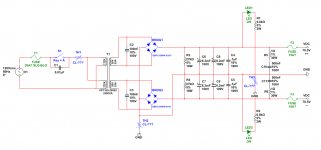
Here's my first take for the Power Supply I´ll be using 11 pairs per OS channel, all ZM Boards, I have some Toshiba 2SA1986/2SC5358 pairs so I will start with those.
I´ll be using a 2500VA Toroidal and I hope 124mF of filtering per rail are OK, I have a ton of questions but the initials are:
1. The Inrush Current Limiter on the AC Mains, how do I chose an appropriate one for a Transformer this big? The typical CL-XXX series only go to 16A (CL-101) with .5 Ohm resistance but, should I go with something bigger? I have some Anthem brand that are 30A with .3 Ohm resistance and 50A with .5 ohm resistance.
2. I have seen Papa using either CL-40 or RC Parallel network to connect to chassis ground on his Adcom designs so I added that, what´s better? If the Inrush Current limiter is, what value do you suggest?
3. I added only one little snubber 100nF cap per bridge rectifier just as a textbook value but I intend to make improvements later on when I have time to build Mark´s Quasimodo test-jig, anything better you can recommend in the meantime? Is the typical RC network (0.1uF + 1R) in parallel per rectifier diode worth it?
4. I also added 2 symmetrical RC networks at the end for any residual capacitor inductance but again, only used textbook values, are they OK or no need for that?
Thanks in Advance!
Edit: I just noticed that I put 6.2mF instead of 62mF in the schematic. Sorry...
Attachments
Last edited:
1. buy hefty soft start module which is bypassing resistors/NTCs after start-up
2.use NTC+bridge+cap combo
3. mu
4. mu
2.use NTC+bridge+cap combo
3. mu
4. mu


Mark, for soft start and a bunch of related goodies, check out:
PCB: low voltage On-Off switch drives AC mains relay \ includes soft start .. H9KPXG
PCB: low voltage On-Off switch drives AC mains relay \ includes soft start .. H9KPXG
Mark, for soft start and a bunch of related goodies, check out:
PCB: low voltage On-Off switch drives AC mains relay \ includes soft start .. H9KPXG
That's the one I've built to use in my Stasis amp 🙂
I'm still waiting for the amp case to arrive. 🙁
Thanks folks, it’s hard to find any readily available module that’s advertised both for 120V Mains and capable of handling up to a 2.5kVA Transformer, I found this one from another Alex that seems to work using the relay/resistors combination plus a time delay circuit, I think I’ll give it a try!
Soft-start, Inrush Current Limiter for toroidal transformers-assembled, tested | eBay
Soft-start, Inrush Current Limiter for toroidal transformers-assembled, tested | eBay
If you use that PCB from eBay, you'll still need to find a power on/off switch whose contacts are rated to handle a steady state current of 20 amperes (2.5 kVA when AC mains is 120V). That PCB doesn't switch the AC on and off, it merely implements a current limiting resistor + time delay, when an (external) switch first turns on.
I also think it you would find it highly beneficial to study Cornell Dubilier's "Quencharc" product line, and all of their supporting technical information, when dealing with 20 ampere switches. And remove all rings, watches, and metal jewelry before servicing the equipment!
I also think it you would find it highly beneficial to study Cornell Dubilier's "Quencharc" product line, and all of their supporting technical information, when dealing with 20 ampere switches. And remove all rings, watches, and metal jewelry before servicing the equipment!
... I found this one from another Alex that seems to work using the relay/resistors combination plus a time delay circuit, I think I’ll give it a try!...
Should work.
... you'll still need to find a power on/off switch whose contacts are rated to handle a steady state current of 20 amperes (2.5 kVA when AC mains is 120V)...
It's the upper limit of plain old toggle switches, but still available off the shelf at affordable prices. And yes, using a spark suppressor/snubber would be a good idea: it reminds me of the old days when people used compressed air to blow away the spark. I don't know what they do nowadays, probably the same trick when dealing with high power. 🙂
Thanks Mark and Zung, yes the switch is something I’ve been thinking about since I started looking at this big Toroidal specially because I’m using Pico’s Ultimate Enclosure and it comes with that big opening on the back for Schurter power entry module and those only go up to 10A, at least that’s what I’ve found, I have others Filtered from TE Connectivity that go up to 15A but aren’t a perfect fit for the hole, they run a bit small.
Mark, with that being said I like your solution much better since it handles that in a better way but I’ll have to find the 5V source and would it handle that cake of a Toroidal and if so do you still have any boards left? It’s been almost a year...
Mark, with that being said I like your solution much better since it handles that in a better way but I’ll have to find the 5V source and would it handle that cake of a Toroidal and if so do you still have any boards left? It’s been almost a year...
Last edited:
You can always use a front panel switch to control a relay coil, which in turn whose suitably sized contacts can switch the transformer primary.
You can still use a soft start and DC blocker as required.
You can still use a soft start and DC blocker as required.
Folks, I don't expect to be using this transformer's capacity nor the in general amplifier's capacity right away but I still want to build it knowing that if one day I come across a pair of say "Thiel CS5" speakers or alike, or if I build a hard to drive set of them it will be able to drive them, while I find a proper power input/switch module I will have to use the normal Schurter ones that are rated for 10A but in your experience, is that a good idea or due to the transformer's size is not possible, even when used with 8 ohm load at say 200W per channel max?
buy either solid state relay , or hefty mains relay with coil for your mains voltage
industrial ones are cheap and will last years
industrial ones are cheap and will last years
diyAudio PCB free gerbers "H9KPXG" includes a footprint for a relay whose contacts are rated only 16 amperes, not 20. Sorry about that. On the bright side, you could instruct the PCB fab to deposit double-thick copper (2 ounces), whereas the eBay board is single thick 1 ounce copper only.
- Home
- Amplifiers
- Pass Labs
- New Stasis front end