18, regulated =) No shunt, don’t be sad, even Zardoz didn’t always get it his way.
Last edited:
ARGH!
Something went wrong.
My WLS was playing perfectly, and I went to the next step, connecting those cinemags to the output (AFAICS, connections are all correct.
I this move, I elevated the linestage by changing the 5 mm standoffs with 10 mm.
I used washers, and one touched R44 (or even shorted it with P2 centerpin, don‘t know…
Fixed this, disconnected everything not ba-18, but: there’s a hum wich wasn‘t there before, and this channel (the P2 one…) is misbehaving: aside the hum it is mute. When I disconnect it, hum doubles (or halves, don‘t remember)
I checked if the trimpot was damaged by checking offset, seems fine and stable…
I‘m sorry, I won’t be able to do further test until tomorrow, but, where could I look for what?
Many thanks
David
Sorry to hear that, David!
If it is any comfort, as you know I made a mistake too, and am still struggling with it. So I actually ordered new boards...
I am therefore not the one to help you here. Help from a blind man...
That said, I too have experienced hum, when the CCS is misbehaving. Measuring voltage drop scross R1 and R2 provided some insight for me. I suspect that might prove some insight for you too. ZM advised that in an earlier post. You could compare drop with the working channel. And check that it is in fact constant, and as equal as possible across R1 and 2. I am struggling with getting the CCS on one side / one pair of JFETs constant. But might not be your issue at all...
ZM’s post from two days ago advises checking drop across R7 and the 27R resistor at the outputs. Maybe that will tell you where it dies, I dunno...
But if your offset is stable, maybe none of those tests will be relevant, come to think of it.
I hope you solve it, David! If you need new active devices, I have literally hundreds. Just give me a chime if you need some.
Regards,
Andy
Last edited:
Yeah, I‘ll look forward to see what it is. The infidel little bugger… frzzrgrmbl.
[emoji849][emoji3061]
[emoji849][emoji3061]
into the beast
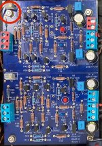
So I started to, uhm, investigate? Not that I'm really could do so in the circuitry...
Looking after Andy's troubles and MMZM's requires for values, measuring V across resistors R1 R11 and R7 R11 ...
Does that mean that I put one needle onto R1 and the other onto R11? What side?
PS: Those resistors in a red square... aren't tagged...
Attachments

I would first turn on for a few minutes
Then measure across resistors and note values and if there is drift. Drift at R1 and/or 2 will affect offset, so maybe you are good if it actually zeroes like you said. Across meaning both pins on either side of one resistor, at a time, like when biasing an output stage.
If anything, this might rule out JFET issues?
How about starting with voltage drop/potential drift across:
R1
R2
Then:
R7
R11
Then:
R13
R12
With offset zeroed.
Note values and compare with other channel.
If you can’t find anything there, you have at least excluded a few things, maybe?
Maybe you could measure drops across all the resistors and compare with other side, but I guess that whatever you find out you need either Full Nelson, 6L6, Mighty, Mark or Dennis or the likes to help you interpret. I am not capable of that, especially seeing as I don’t even have the skills to get my own WLS going without hickups 🙁
Last edited:
I am not the one to thank, but thanks!
Zardoz aka Mighty is my source of this «knowledge». Haha
Zardoz aka Mighty is my source of this «knowledge». Haha
Something went wrong.
I used washers, and one touched R44 (or even shorted it with P2 centerpin, don‘t know…
Fixed this, disconnected everything not ba-18, but: there’s a hum wich wasn‘t there before, and this channel (the P2 one…) is misbehaving: aside the hum it is mute. When I disconnect it, hum doubles (or halves, don‘t remember)
Many thanks
David
Just for clarification:
1: P2 do you mean P1?
2: R44, where is that resistor? I know the other channel has different values printed on the PCB, just cant remember them all.
3: When you disconnect it is quiet. Can you describe what you disconnect? Signal wires, or DC?
4: remember to short inputs for your tests.
Good luck! Hoping for quick solution! Bipolars are ready to ship if that is you source of error.
Hugz,
Andy
Last edited:

Ok, here we go:
PSU is VRDN, denoiser jumpered.
------ CH1 working -----
-18.00 / +18.02 VDC, offset -2mV +- 1mV
R1 — 21.15 mV
R2 — 21.44 mV stabilized after 30" — down from 21.49 mV
R7 - 1.409 V
R11 - 352.6 mV
R13 - 1.408 V
------ CH2 not working -----
-18.00 / +18.02 VDC, offset -0.5 mV +-1 mV
R1 [R27] — 350.6 mV stabilized after 30" — down from 351.0 mV
R2 [R28] — 20.75 mV stabilized after 30" — down from 20.78 mV
R7 [R38] - 1.402 V
R11 [R32] — 350.6 mV stabilized after 30" — down from 351 mV
R13 [R31] - 1.393 V stabilized after 30" — up from 1.391 V
Looking at this, and thinking of how well it played before, I would guess the board's fine, and something else is bad. But I have no idea where the baddie could hide.
If I remember correctly, it's the nonworking channel that got the power reversed once—C5[C12] blew and was replaced...
Last edited:
The voltage across R27 is 15 times higher than R1, R2 and R28, meaning that there is 15x more current through R27. Looks like you have a problem with Q1 or maybe Q5.
Something went wrong.
My WLS was playing perfectly, and I went to the next step, connecting those cinemags to the output (AFAICS, connections are all correct.
---------------
---------------
Many thanks
David
Go back to the original working state...i.e. take out the cinemas and extended stand offs. THEN measure as suggested by others. IF working as previous to the changes you made then start again if you insist on including transformers. BUT first ensure that you have correctly installed the Tx having checked that the 'bad side' Tx measures as per makers spec.
Thank you to both!
I already did so, except the 10mm standoffs are still here, but this time verified.
It's basically Linestage + PSU.
No input-selector nor pot...
😱 Erm... I messed up with the notes:
R27 is actually 20.94
I think I should repeat the measurement's table, do you mind if I open up a new thread for this specific debugging-process, and have the previous posts concerning my WLSBA18-problem transferred?
Apologies for bungling, it's the nervosity—or something...
original working state...i.e. take out the cinemas
I already did so, except the 10mm standoffs are still here, but this time verified.
It's basically Linestage + PSU.
No input-selector nor pot...
The voltage across R27
😱 Erm... I messed up with the notes:
R27 is actually 20.94
I think I should repeat the measurement's table, do you mind if I open up a new thread for this specific debugging-process, and have the previous posts concerning my WLSBA18-problem transferred?
Apologies for bungling, it's the nervosity—or something...
If you shorted R44 to the center pin of P2, which I suspect, you put +rail voltage on the input of Q1, more than likely frying it and possibly more, especially Q5. R44 is the same as R20 on the other channel and P2 is the same as P1 on the other channel. If you look at the circuit diagram on the first post, you will see what I'm talking about.
Ok, here we go:
PSU is VRDN, denoiser jumpered.
------ CH1 working -----
-18.00 / +18.02 VDC, offset -2mV +- 1mV
R1 — 21.15 mV
R2 — 21.44 mV stabilized after 30" — down from 21.49 mV
R7 - 1.409 V
R11 - 352.6 mV
R13 - 1.408 V
------ CH2 not working -----
-18.00 / +18.02 VDC, offset -0.5 mV +-1 mV
R1 [R27] — 350.6 mV stabilized after 30" — down from 351.0 mV
R2 [R28] — 20.75 mV stabilized after 30" — down from 20.78 mV
R7 [R38] - 1.402 V
R11 [R32] — 350.6 mV stabilized after 30" — down from 351 mV
R13 [R31] - 1.393 V stabilized after 30" — up from 1.391 V
Looking at this, and thinking of how well it played before, I would guess the board's fine, and something else is bad. But I have no idea where the baddie could hide.
If I remember correctly, it's the nonworking channel that got the power reversed once—C5[C12] blew and was replaced...
Im just going to throw this out there. *Note* i am far from expert. My thought is Q1 and/or Q5 is fried.
Just grounding R44 with the standoff would not hurt anything. The same as shorting the input to measure something.
BTW, with the VRDN board, if the the jumper is in place, the denoiser is disengaged and you are running a straight LM3*7 with adj. cap.
Since the standoff is probably grounded, you also shorted the + rail to ground. It may not have hurt the circuit at all. Your issue may be the power supply.
Didn't you use dual mono VRDN boards? If so, a quick check would be to switch the boards on the power supply boards.
Since the standoff is probably grounded, you also shorted the + rail to ground. It may not have hurt the circuit at all. Your issue may be the power supply.
Didn't you use dual mono VRDN boards? If so, a quick check would be to switch the boards on the power supply boards.
- Home
- Amplifiers
- Pass Labs
- Wayne's BA 2018 linestage