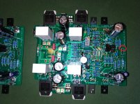
Finally plugged the amp into my home office HiFi system.
Currently no input caps which I'll get back to some when I build a second set on amp modules.
There's some hum with the RCA cord attached but zero without (dead as a dodo). Will have to trace the wiring back to the other components.
Preliminary observations, playing through old Celestion DL6s, and compared to the 15W JLH I built a few years back:
1) Bass control is far superior. I was getting some 'motor-mower' affect with the JLHs on music with a low frequency content. No problem here, well controlled bass.
2) Middle registers about the same maybe the xK's have an advantage here.
3) Upper registers about the same.
These comments are based on limited listening playing MP3s via my PC (Asus sound card) and a JLH headphone amp (As a volume control). Also played Santa Esmeralda "Don't let me be misunderstood" from my Turntable (Technics with SME arm, Pearl cartridge) to check the lower registers (home made RIAA amp based on the Hagerman).
As mentioned at the outset, a very limited test thus far. Will continue playing some more MP3s and (a better test) some LPs and revert.
🙂 good one Tony
Fantastic that you’ve powered this thing up and you’re getting music now.
Hopefully the hum will get sorted out.
Fantastic that you’ve powered this thing up and you’re getting music now.
Hopefully the hum will get sorted out.
First test: Channel One 450 mV between R12 / R13, stable. Channel Two 650 mV and increases, I have turned off.😡
Channel two: the bias is too high between Q8 and Q9. Bias is regular between Q5 and Q6 (400 mV). Have you suggestions, for me? Thanks.
Last edited:
Channel two: the bias is too high between Q8 and Q9. Bias is regular between Q5 and Q6 (400 mV). Have you suggestions, for me? Thanks.
Are you running in Class AAB or Class A?
Are the amps connected in your chassis or are you just running on a 'test bed' at the moment?
Class A, with input short, no load. No chassis. Yes heatsink.
Have you checked the other voltages as per those stated on Page 15 of the build guide? Perhaps you can run in Class AAB mode to limit the output currents whilst checking them (if you haven't already)?
Have you got the bias setting resistors swapped by any chance on one of the amps? So one is running class A and the other AAB?
Also, check the SMD capacitors around the bias controller. If the one across the base <> emitter was leaky, it would cause the output bias current to be higher that it should be.
(Good idea Tony! - run in AAB to debug)
Also, check the SMD capacitors around the bias controller. If the one across the base <> emitter was leaky, it would cause the output bias current to be higher that it should be.
(Good idea Tony! - run in AAB to debug)
Last edited:
I'm stupid!😡
Q9 was not strongly heatsink fixated. Now it's a little black but it works,
bias is stopped at 400 mV. Should I replace it?


Q9 was not strongly heatsink fixated. Now it's a little black but it works,
bias is stopped at 400 mV. Should I replace it?
Last edited:
I would replace it just to be safe.
Indeed, if one of the drivers or OPS is not heatsink Ed properly and as a result gets very hot, it will cause the problem you have noted ie high bias current.
🙂
Indeed, if one of the drivers or OPS is not heatsink Ed properly and as a result gets very hot, it will cause the problem you have noted ie high bias current.
🙂
kx runs at + - 22 volts DC, class AAB (I don't have 8 ohms speakers, only 4 ohms). I am happy with it. I would like to know what to connect in SIG 0V.
Thank you Bonsai.

Thank you Bonsai.
Last edited:
J1and J2 go to the amplifier module 0 V
You should be able run into 4 ohms in class A on +- 22 V rails without problems. The amp will transfer to class AAB when the current demand exceeds about 600 mA per output pair.
On 35 V supply rails, ( much higher than your 22 V) the standing dissipation is too high for class A.
You should be able run into 4 ohms in class A on +- 22 V rails without problems. The amp will transfer to class AAB when the current demand exceeds about 600 mA per output pair.
On 35 V supply rails, ( much higher than your 22 V) the standing dissipation is too high for class A.
Last edited:
Sorry - please ignore post #872. You should already have the J4 0V to the modules via J11 and J12. J13 is a spare for in case you do not want to use the ground lifter.
The remaining 0V connectors J1 and J2 are spares for any auxiliary circuit you may have - normally you will not need them.
The remaining 0V connectors J1 and J2 are spares for any auxiliary circuit you may have - normally you will not need them.
Last edited:
Ok.Sorry - please ignore post #872. You should already have the J4 0V to the modules via J11 and J12. J13 is a spare for in case you do not want to use the ground lifter.
The remaining 0V connectors J1 and J2 are spares for any auxiliary circuit you may have - normally you will not need them.
My left channel runs at 300 mA and the right channel at 350 mA bias in class AAB. How can I make them equal?
J1and J2 go to the amplifier module 0 V
You should be able run into 4 ohms in class A on +- 22 V rails without problems. The amp will transfer to class AAB when the current demand exceeds about 600 mA per output pair.
On 35 V supply rails, ( much higher than your 22 V) the standing dissipation is too high for class A.
I replaced a better transformer but 15 volts AC. It drives 4 ohm speakers very well in class A.🙂
Ok.
My left channel runs at 300 mA and the right channel at 350 mA bias in class AAB. How can I make them equal?
There are a lot of variables that determine the OPS current. The 0.33 ohms resistor tolerances, OP transistor Vbe’s and the control transistor Vbe. Exact matching between channels would require a pot, and I wanted to keep the design simple and minimize adjustments.
In practice, because the standing current, even in class AAB, is very high, it will not make any material difference in practice - about 0.2dB difference in class A power over the full power range of the amp.
Ok.
My left channel runs at 300 mA and the right channel at 350 mA bias in class AAB. How can I make them equal?
Open to correction from others but I think your quiescent current will increase with transistor temperature.
If the thermal resistance between your output transistors and the heatsink is high, or if your heatsinks are small, then you might get higher than expected quiescent currents.
So, if you can, perhaps measure the temperatures of your transistors and the heatsinks. For lowest thermal resistance you want the smallest difference in temperatures you can get.
Ditto, the heatsink temperature to ambient temperature difference should be as low as possible.
In my ±32V setup, class AAB, I get only 15°C difference between heatsink temperature and ambient temperature after about 1/2 hour warm up (no load) and pretty much 200ma per channel on the dot. But then I'm using a large 4U case with low thermal resistance (0.38 °C/W per heatsink and 2 heatsinks per side - each amp on one heatsink only).
Didn't measure the transistor temperatures on build finalisation though 🙁
Good points Tony!
If there is a temp imbalance, say due to not quite the same heat sinking (maybe too much heatsink paste for example, or maybe not enough) you will get differences in current due to the Vbe differences due to thermal imbalance. If the difference is due to assembly/heat sinking it must be resolved. The problem will be worse at higher standing currents.
That said, there is still the opportunity for Iq spread for the reasons I mentioned earlier
🙂
Last edited:
Good points Tony!
If there is a temp imbalance, say due to not quite the same heat sinking (maybe too much heatsink paste for example, or maybe not enough) you will get differences in current due to the Vbe differences due to thermal imbalance. If the difference is due to assembly/heat sinking it must be resolved. The problem will be worse at higher standing currents.
That said, there is still the opportunity for Iq spread for the reasons I mentioned earlier
🙂
From somewhere in my (very distant) past readings I seem to remember that the servo bias transistor was mounted on the heatsink to stabilise the quiescent current on some designs.
Probably specific to the topology I guess and I (or rather my memory) may be completely wrong. 🙁
Anyway, it was just a thought that came to mind that might help.
- Home
- Amplifiers
- Solid State
- Hifisonix kx-Amplifier