Tony, just Somali can understand, the PP is in electrical contact with the chassis via the screws that are clamping it through the nylon stand-off’s?
Are you running any additional ground wire to the PP?
Are you running any additional ground wire to the PP?
Tony, just Somali can understand, the PP is in electrical contact with the chassis via the screws that are clamping it through the nylon stand-off’s?
Are you running any additional ground wire to the PP?
Hi Bonsai,
The perforated plate is 'floating' because it is electrically isolated from the case/chassis being mounted with nylon stand-offs.
The main earth from the IEC socket is connected to the perforated base.
The (dual - it's a 25-0, 25-0 transformer) '0V' line of the transformer secondary is connected to the same earth point on the perforated plate.
There is a separate earth wire from the perforated plate to the chassis so the case itself is connected to the main earth too.
In other words it's an star earth point on the perforated plate (PP) e.g.
1. IEC socket to PP star earth point
2. PP Star earth point to '0V' transformer secondary
3. PP Star Earth point to case/chassis.
So all internal earthing runs from the same connection on the perforated plate.
I did some more work on my amp yesterday which I'll confirm and write up later but, in short:
1. The (20 year?) old 2.2nF polystyrene caps were a major part of the problem. The new ceramics are far better in reducing the oscillation 'envelope' I was getting. These RCA caps are connected from the (isolated) RCA ground to the chassis/case - not the perforated plate.
2. Instead of a direct earth connection to the chassis/case, replacing it with a ground lift (back to back diodes only) between the PP and the chassis works best at reducing 50/100 Hz 'spikes' from the amp outputs as viewed on my scope.
In other words the case itself is 'ground lifted' rather than the PP or DC '0V' line. Probably work the other way round - Main earth to chassis, PP ground lifted from Chassis (haven't tried yet). I assume these 'spikes' are from the bridge rectifiers turning on and off?
Anyway, yesterday was a day of 'fiddling around' to see 'what happens if ..." to get the best results across the frequency spectrum.
I'll try and 'document' it more precisely for the forum.
Cheers
Chassis earthing with internal perforated plate
The earthing arrangement I've been trying is as per the "General Earthing" JPG attached.
The incoming mains IEC socket has a metal, earthed casing which has been isolated from the chassis rear panel (electrical tape) to prevent any earth loop with the mains earth from the IEC's 'push on' earth plug.
The earth from the IEC socket goes directly to a star earth on the perforated plate (PP).
The PP is mounted to the chassis using 4 by 12mm nylon spacers - and thus insulated from the chassis per se.
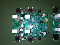
The PP star earth is permanently connected to the transformer secondary '0V' line at the middle terminal block to the right of the transformer. This terminal block also connects the transformer secondary AC lines to the Ripple Eaters.
The terminal block above (with the red caps) is a snubber network.
Below the middle terminal block is a 'splitter' terminal block that divides the transformer AC - 0V - AC secondary into two sets which feed 4 separate fuses (below, off picture) - one set for each AC line to the two Ripple Eaters.
The transformer secondary 0V line is common to both Ripple Eaters.
At the right rear, the right hand RCA cap has been connected between the RCA earth and the chassis corner.
As above, there is no earth connection from the PP to the chassis/case.
I ran three sets of tests at 3 different scope timebases:
1. With the only mains ground connection to the perforated plate ("PP Earth Only")
2. With the chassis connected to the perforated base star earth ("Chassis Earthed via PP").
3. With the chassis connected from the PP star earth by means of 'back to back' diodes (i.e. a 'ground lift') ("Chassis GL via PP").
Each set-up was evaluated at 10ms, 25us and 50ns timebase settings - simply because these timebases (or similar) have been where I have previously found waveforms without any input.
Otherwise:
Running class AAB on ±32.5V rails, amplifiers unloaded.
Input shorted, probe @ X1
All scopes are taken as 'single shot' - i.e. basically 'freeze frame' - and not averaged readings (which are much better - but I was looking at 'instantaneous waveforms' and how the DC supply performed)
I think it's useful to compare the 3 different 'earth arrangements' at each timebase setting:
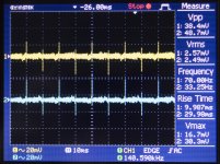
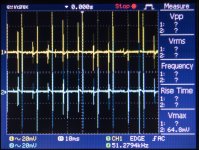
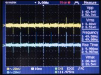
10ms 20 mV
Both the 'PP Earth Only' and 'Chassis GL via PP' look very similar.
The "Chassis earthed via PP" (i.e. direct connection between PP star earth and Chassis) was inferior
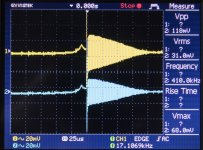
25us
"PP Earth Only" looks very good with a horizontal scale of 2mV/Div
"Chassis Earthed via PP" doesn't look at all good even at 25mV/Div but better than I was getting with my (old) 2.2nF polystyrene caps.
"Chassis GL via PP" at 25 mV/Div looks inferior to the "PP Earth Only" but far better than connecting the chassis direct to the PP star earth
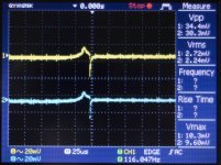
50ns
"PP Earth only" and "Chassis Earthed via PP" look similar at 2mV/Div However there was a spurious sine waveform that transiently appeared with the "Chassis Earthed via PP" which I managed to capture (by taking 'single shot scans' repeatedly until I captured it) at 20mV/Div. This doesn't show up with the other 2 earthing schemes and no idea where it's coming from.
"Chassis GL via PP" was almost identical to the "PP Earth Only" - but I've reached the DIY audio limit on attachments so I can't add it.
The above are my current findings based on my transformer and setup. Others might not get the same results with their setups so mine are just for information purposes.
BTW, the Ripple Eaters ground lift points were not used in all tests.
I'll also try taking the mains earth direct to the chassis and then ground lift the perforated plate and see what happens.
Questions/ comments/recommendations welcomed.
Cheers
The earthing arrangement I've been trying is as per the "General Earthing" JPG attached.
The incoming mains IEC socket has a metal, earthed casing which has been isolated from the chassis rear panel (electrical tape) to prevent any earth loop with the mains earth from the IEC's 'push on' earth plug.
The earth from the IEC socket goes directly to a star earth on the perforated plate (PP).
The PP is mounted to the chassis using 4 by 12mm nylon spacers - and thus insulated from the chassis per se.
The PP star earth is permanently connected to the transformer secondary '0V' line at the middle terminal block to the right of the transformer. This terminal block also connects the transformer secondary AC lines to the Ripple Eaters.
The terminal block above (with the red caps) is a snubber network.
Below the middle terminal block is a 'splitter' terminal block that divides the transformer AC - 0V - AC secondary into two sets which feed 4 separate fuses (below, off picture) - one set for each AC line to the two Ripple Eaters.
The transformer secondary 0V line is common to both Ripple Eaters.
At the right rear, the right hand RCA cap has been connected between the RCA earth and the chassis corner.
As above, there is no earth connection from the PP to the chassis/case.
I ran three sets of tests at 3 different scope timebases:
1. With the only mains ground connection to the perforated plate ("PP Earth Only")
2. With the chassis connected to the perforated base star earth ("Chassis Earthed via PP").
3. With the chassis connected from the PP star earth by means of 'back to back' diodes (i.e. a 'ground lift') ("Chassis GL via PP").
Each set-up was evaluated at 10ms, 25us and 50ns timebase settings - simply because these timebases (or similar) have been where I have previously found waveforms without any input.
Otherwise:
Running class AAB on ±32.5V rails, amplifiers unloaded.
Input shorted, probe @ X1
All scopes are taken as 'single shot' - i.e. basically 'freeze frame' - and not averaged readings (which are much better - but I was looking at 'instantaneous waveforms' and how the DC supply performed)
I think it's useful to compare the 3 different 'earth arrangements' at each timebase setting:
10ms 20 mV
Both the 'PP Earth Only' and 'Chassis GL via PP' look very similar.
The "Chassis earthed via PP" (i.e. direct connection between PP star earth and Chassis) was inferior
25us
"PP Earth Only" looks very good with a horizontal scale of 2mV/Div
"Chassis Earthed via PP" doesn't look at all good even at 25mV/Div but better than I was getting with my (old) 2.2nF polystyrene caps.
"Chassis GL via PP" at 25 mV/Div looks inferior to the "PP Earth Only" but far better than connecting the chassis direct to the PP star earth
50ns
"PP Earth only" and "Chassis Earthed via PP" look similar at 2mV/Div However there was a spurious sine waveform that transiently appeared with the "Chassis Earthed via PP" which I managed to capture (by taking 'single shot scans' repeatedly until I captured it) at 20mV/Div. This doesn't show up with the other 2 earthing schemes and no idea where it's coming from.
"Chassis GL via PP" was almost identical to the "PP Earth Only" - but I've reached the DIY audio limit on attachments so I can't add it.
The above are my current findings based on my transformer and setup. Others might not get the same results with their setups so mine are just for information purposes.
BTW, the Ripple Eaters ground lift points were not used in all tests.
I'll also try taking the mains earth direct to the chassis and then ground lift the perforated plate and see what happens.
Questions/ comments/recommendations welcomed.
Cheers
Attachments
-
 PP Earth Only 10ms 20mv.jpg561.8 KB · Views: 203
 -
 Chassis Earthed via PP 10ms 20mv.jpg753.9 KB · Views: 216
 -
 Chassis GL via PP 10ms 20mv.jpg696.1 KB · Views: 202
 -
 PP Earth Only 25us 2mv.jpg646 KB · Views: 190
 -
 Chassis Earthed via PP 25us 20mv.jpg691.9 KB · Views: 187
 -
 Chassis GL via PP 25us 20mv.jpg625.1 KB · Views: 63
 -
 Chassis Earthed via PP 50ns 20mv #2.jpg748.4 KB · Views: 71
 -
 Chassis Earthed via PP 50ns 2mv #1.jpg793.8 KB · Views: 57
 -
 PP Earth Only 50ns 2mv.jpg664.9 KB · Views: 56

To continue:
I tried grounding the chassis then a direct ground to the perforated plate star ground.
This resulted in Channel A (Left side amp) voltage across R14/R15 jumping to > 700 mV (normal ± 200mV) within seconds.
I interposed the back/back diode ground lift between chassis ground to the PP star point. Voltage across Channel A was somewhat larger ± 190 mV but the waveform was poor - similar to picture 5 in post 843 but a somewhat more 'rounded' envelope.
Disconnected the 2 fuses to Channel B (Right side amp) and also the secondary '0V' line to the Ripple Eater: And Channel 'A' returned back to normal (essentially a 'flat trace')
Back to the drawing board.
Removed the RCA caps and no matter what configuration I use - ground to PP then to chassis, ground to chassis and then to the PP star point, no ground between chassis and the PP, with or without the addition of a ground lift, the scope trace is essentially flat from 100ms to 1ns with RMS voltages < 1mV, without resorting to trace averaging at all.
I doubt it could be any better.
The proof, of course, is when I remove the dummy input plugs, attach the signal generator and see what happens (incoming RF from the signal generator leads - which the caps are there to prevent I think).
Then check the sine and square waveforms with one channel loaded with my dummy 8.2 ohm speaker load.
So, ultimately, there seems to be some feedback occurring between the 2 RCA input grounds with the caps attached. Certainly it's not a 'ground loop' but there seems to be an HF loop created? 😕
Not sure why I'm the only one having this problem. Maybe the RCA caps would be better if placed between the incoming RCA live and ground?
If I understand your scope plots correctly, these HF ringing issues are happening at the mains zero crossing points and the result is you are getting oscillatory bursts when you zoom the time base in.
Please do the following:1
1. Connect the scope probe to your amplifier power supply so that you can see these bursts on the trace (use AC mode coupling)
2. Turn your amplifier off
3. Confirm that the busts are still present/not present
If still present with the amplifier OFF, the problem is not in your amp. If they go away, I would think this is diode switch off ringing either on your main bridge rectifier, or on your soft start board. In either case, this can be mitigated with a snubber network.
Your grounding/earth loop wiring will have little impact on this issue since the coupling mechanism is going top be primarily capacitive in this case.
If I understand your scope plots correctly, these HF ringing issues are happening at the mains zero crossing points and the result is you are getting oscillatory bursts when you zoom the time base in.
Please do the following:1
1. Connect the scope probe to your amplifier power supply so that you can see these bursts on the trace (use AC mode coupling)
2. Turn your amplifier off
3. Confirm that the busts are still present/not present
If still present with the amplifier OFF, the problem is not in your amp. If they go away, I would think this is diode switch off ringing either on your main bridge rectifier, or on your soft start board. In either case, this can be mitigated with a snubber network.
Your grounding/earth loop wiring will have little impact on this issue since the coupling mechanism is going top be primarily capacitive in this case.
Hi Bonsai,
Thanks for your reply.
Not exactly sure what you wanted here but did the following:
1) Connected the 2 2.2nF RCA caps between RCA ground and chassis.
2) Connected the incoming mains earth/ground to case/chassis. Connected chassis to PP star ground to induce this 'ringing' effect.
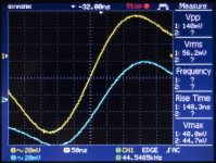
3) Measured the left hand amp output as well as the positive and negative line outs from the Ripple Eater. Probe earths were connected at the amp 'return' line and Ripple Eater '0V' lines respectively.
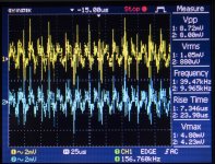
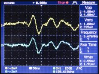
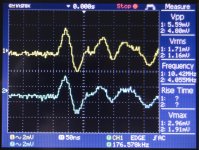
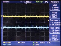
4) The Yellow trace is the amp output, Blue the Ripple Eater positive and negative lines (separately measured as I only have a 2 channel scope)
5) Powered up and recorded the two above traces (attached). The RE 'pulse' is around 1/10th that of the left hand amp (note the different scales on the traces, 1V Amp vs 100mV for the RE) for both negative and positive RE output lines.
6) Turning off the amp both waveforms collapse immediately. Only the noise component is left (i.e., both are 'straight lines', no waveforms).
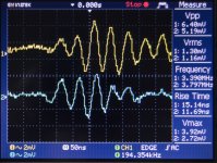
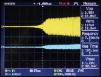
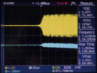
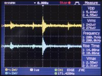
7) Disconnected the left hand amp from the RE, and checked both positive and negative lines with the power on. Again, no waveform at 25us. The only one I could find was down at 1us. Pics of both attached.
Not sure if you can make anything of these results?
Attachments
To summarize (so I can check that I’ve got this right) with both channels running, both amp outputs shows ringing at a few mV at the mains cross over points, and the supply rails show it at about 10x lower. If you disconnect one of the amp channels, the problem disappears.
Please make sure for the tests below the inputs to both amps are shorted.
1. Can you check that if you power up the left channel amp a d disconnect the right channel amp you get the same result ie there is no ringing
2. Separately after that, shorty the collector to emitter on both + and - on the RE and repeat the test.
3. Is this issue still present when you have the 2.2 nF RFI caps in situ?
(Are you doing these tests with or without a load ?)
Last edited:
Hi Bonsai,
1) If the right channel is disconnected (pulled fuses - '0V' line still connected) then the ringing continues. If I also pull the '0V' connector off the right channel the ringing stops.
2) I've now disconnected the caps again and wired up the earthing.
3) Yes with the 2.2 nF caps connected. If I disconnect just one cap the ringing goes away - which is why I thought it was some form of 'RF loop'.
4) No load connected yet. As remarked previously adding a load (even my 8.2 Ohm/4mH one) makes a marginal improvement but doesn't stop it.
Looking at points 1 & 3 one has:
Left RCA Gnd-> Left Amp 0V -> Left RE 0V -> Terminal block 0V -> Right RE 0V -> Right Amp 0V -> Right RCA Gnd
This works OK.
Adding both caps one then also forms:
Left RCA Gnd -> Left RCA Cap ->Chassis -> Right RCA Cap -> Right RCA Gnd
Thus forming a circular loop when added to the first 'connection scheme'.
Removing just one RCA cap breaks the 'ringing'.
Or
Removing the '0V' line from the right hand (unpowered) RE breaks the 'ringing'.
It might be because, tracing the RCA caps back, one is essentially adding them across the transformer secondary '0V' line to earth ground?
Because I have a snubber attached at the transformer secondaries this might also be a cause of the problems?
BTW, the 1us waveform is there whether the power is on or off - so seems to be something the scope probes themselves are picking up, nothing to do with the amp.
Right now I'm running further tests without the RCA caps and see what happens. If I don't find any problems, I'll stick to this configuration. 🙂
Tony,
IIRC you had the input connectors on opposite sides of the rear panel. If this is the case, the input RFI caps in conjunction with the HBR will be susceptible to picking up HF as a loop is formed with the closure being completed by the rear panel metalwork. So indeed, when you remove one of the caps, you break the loop. I would do this.
As to the HF ringing, I can only guess that it’s either from the main bridge rectifier, or if you have one on your soft start, it’s coming from there.
The snubber per Mark Johnson must be placed as close as possible to the rectifier. If it is inches away, the snubber current will be flowing through the wires between tne snubber and the rectifier and because it’s at HF, will easily radiate inside the housing into all the wiring. Best place for the snubber it to solder it directly acoss the bridge terminals with very short leads.
There is a second cap which can go straight across the secondary winding at c. 10 x the snubber cap value and this attenuates HF mains noise - again see the Johnson documents linked to further back in this thread. This will help catch line conducted noise bring generated by other equipment.
BTW, no amount of star grounding, or wire re-routing or chassis panel isolation will help with HF issues like this. Because it’s at such high frequency, it just blasts into everything as common mode noise.
Last edited:
Hi Bonsai,
Yes, it's undoubtedly complex. Must admit I had forgotten about the soft start circuit diodes.
Actually IRO the snubbers I'm using 150nF caps with 39 ohm resistors. They are placed on the transformer secondary as per Mark Johnson's comments in post. However, a little confusion about exactly where they should have been placed. I had assumed "across the Transformer secondaries" meant "at the transformer end" ("Component count is minimized when you place one snubbing resistor across each transformer secondary winding (rather than each diode)."). Re-reading post 690 now I guess he was talking about across the transformer secondaries at the bridge instead of across each bridge diode. 😱
You're possibly right about the 400mm or so separating between the RCA plugs. The idea is to ultimately have 4 amps in the chassis and a 2 way crossover. I'd placed the amps on opposite sides of the chassis to check the thermal dissipation first and minimise the length of RCA cord required internally.
There are actually 2 heatsinks per side in this chassis so they're easy to move around with the amps mounted on them. I would just then 're-order' and add an extra RCA socket per side.
Perhaps I'll re-look at the situation when I get the second pair of amps and add them.
Cheers
I’ll post up a picture in about 1 hour - it’s ok to have your amp modules on opposite sides of the chassis, you just have to keep the input connectors together and run the input wires in a specific way to minimize the loop areas.
For the HF noise problems, the layout in the 2nd slide is also better because it reduces the total loop area. However, because the coupling method is through the electric field (very fast rise times and HF) you have to address the problem at source with the snubbers because this type of noise gets into everything. Just a few pF between the source and the surrounding circuits is enough to cause problems.
Thanks for the additional information Bonsai,
I'll look at how I can improve things.
Regards,
Tony
I'll look at how I can improve things.
Regards,
Tony
Dear Bonsai, thank you very much for your excellent amplifiers. Assembled your amplifiers all work great. Repeatability is good. There were no problems with assembly. Everything is fine !. How do you yourself evaluate in comparison with industrial models of amplifiers( Pioneer 656 , Luxman 410 ... etc) ?
Hello Andriy,
Thanks for your feedback - glad you like your amp and the assembly went well.
I cannot comment on other designs, other than to say that I enjoy listening to my amps!
🙂
Thanks for your feedback - glad you like your amp and the assembly went well.
I cannot comment on other designs, other than to say that I enjoy listening to my amps!
🙂
- Home
- Amplifiers
- Solid State
- Hifisonix kx-Amplifier