Can I put the transformer in a separate box? Is the transformer 2 x18 volts ok for +-23 volts DC with simple ripple eather?
Yes, you can separate the PSU if you want to. Use thick cables between the PSU and the amp modules. On +-23 VDC the amp will still be fine.
🙂
🙂
Something is not right. Transformer 250 VA 2x25 volts, J8 open (AAB mode), 400 mV across R14 / R15! +- 30 volt input simple ripple heather, + - 27 volts in the rail! Heatsink very hot.
35 volt output simple ripple heather without connection.
Even in class A I have a strong voltage drop.
35 volt output simple ripple heather without connection.
Even in class A I have a strong voltage drop.
Last edited:
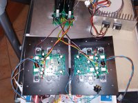
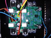
Can you post a photo of your amp, showing the heatsink and PSU?
Attachments
Can you post a photo of your amp, showing the heatsink and PSU?
Is that a flat plate the amplifier is on? I cannot see from the photograph
lamellar heatsink
no.2 x 1,5 kg.
Attachments

Just to check
Supply rail is +-27 VDC = 54 V total
Each pair of transistors is 400 mV = 0.6A = 1.2A per channel
Total standing power dissipation is 54 x 1.2 = 65W
I am guessing your heatsinks are 0.4C/W = 26C temp rise above ambient so for 25C ambient the heatsink temperature will be 51C.
Can you confirm these temperatures are roughly right?
If you lift R18 and leave the bias switch (J8) OPEN the amplifier will go to class AB and the standing current will drop to about 60 mA and it should run cool - if you try that and it does run cool, we can confirm that there is nothing else wrong.
NB: you must connect the Zobel and the Zobel wire has to be twisted tightly with the +- and 0V - this is very important. If you mount the PSU in a separate box, then solder the Zobel (10 Ohm and 0.1 uF 100V film cap) on the amplifier board with short leads. Do not operate the amp without the Zobel!
Last edited:
Hi Bonsai,Just to check
Supply rail is +-27 VDC = 54 V total
Each pair of transistors is 400 mV = 0.6A = 1.2A per channel
Total standing power dissipation is 54 x 1.2 = 65W
I am guessing your heatsinks are 0.4C/W = 26C temp rise above ambient so for 25C ambient the heatsink temperature will be 51C.
Can you confirm these temperatures are roughly right?
If you lift R18 and leave the bias switch (J8) OPEN the amplifier will go to class AB and the standing current will drop to about 60 mA and it should run cool - if you try that and it does run cool, we can confirm that there is nothing else wrong.
NB: you must connect the Zobel and the Zobel wire has to be twisted tightly with the +- and 0V - this is very important. If you mount the PSU in a separate box, then solder the Zobel (10 Ohm and 0.1 uF 100V film cap) on the amplifier board with short leads. Do not operate the amp without the Zobel!
Supply rail: +- 19.5 volts DC
Class A mode
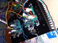
For 20C ambient, heatsinks at 57C/60C (heatsinks in orizontal position on the floor, no case, no natural ventilation).
In A mode I listen to more ambience.
I'm looking for a source, some little saturation problem with high gain mode.
I fit well with an old portable MP3 player.
Hello Davide
In class A mode, the amplifier will run hot. Even on +-19.5 V supply rails, you are still dissipating 50 W per channel.
Your heatsinks are quite small. When you mount them vertically with better airflow and 3-4 cm off the floor, the temperature will drop a few degrees. My kx-Amp runs at about 50 C in class A mode - my heatsinks are about 25-30% bigger than yours from what I can see.
Sorry, I don’t understand the second part of your post - can you explain further?
Hello Davide
In class A mode, the amplifier will run hot. Even on +-19.5 V supply rails, you are still dissipating 50 W per channel.
Your heatsinks are quite small. When you mount them vertically with better airflow and 3-4 cm off the floor, the temperature will drop a few degrees. My kx-Amp runs at about 50 C in class A mode - my heatsinks are about 25-30% bigger than yours from what I can see.
Sorry, I don’t understand the second part of your post - can you explain further?
In A mode I listen to more ambience. (with high bias more detail and air in the music)
I'm looking for a source, some little saturation problem with high gain mode. (R25 15 ohm in my KX. R25 22 ohm is better with preamplifier?)
I fit well with an old portable MP3 player. (my old mp3 player sounds good with KX)
Yes, if you change R25 to 22 Ohm, the gain will reduce from 25x. To 17x which should help with your levels.
Hello everyone. I back from a hiatus and trying to get my Kx Amp up and running again.
I made the modifications listed in Dec 2020 Update in the original post including the Rallyfinnen cap. I’ve re-verified all the mods to the boards.
The right channel bias is much higher than the left. Even the left is higher than the assembly guide.
In the schematic below I recorded voltage measurements of the two channels. The right channel is in parenthesizes. All measurements were made with both channels running after about a 15 minute warm-up period and with the J8 jumpers out. I did make two measurements on the right channel with the J8 jumper in. These are the 541 and 526 mV readings at the far right. I don’t see anything obviously wrong, except that the bias is slightly high in the left channel and very high in the right. Any thought as to what’s going on?
Thanks
Bob
Attachments
Seems to be abt 10% variation, so I'm guessing nothing is 'wrong' just some tolerances?
Did you compare Q7 hfe/Vbe between the channels?
Another way would be to just tune the bias setting resistors (R1 & R18) to get the same currents in both channels.
Did you compare Q7 hfe/Vbe between the channels?
Another way would be to just tune the bias setting resistors (R1 & R18) to get the same currents in both channels.
Rocksteady, these tolerances are all within spec. For the OPS, the 0.33 ohm resistors and the associated resistor ps around Q7 set the standing current. Fives tne spread in values, it’s quite easy to have the range in values you see between the two modules.
Your amps look good!
(I left out ab OPS bias adjustment pot to keep th3 design clean and simplify set up).
Your amps look good!
(I left out ab OPS bias adjustment pot to keep th3 design clean and simplify set up).
Rallyfinnen and Bonsai, thank you for looking this over so quickly and providing responses.
I was concerned as the voltages across the output resistors are well outside those specified.
I did not think to measure any of the transistors before assembling. I guess I missed measuring Q7 in circuit.
I'll play around with R1/R18 to adjust the bias to get the nominal voltages specified on the schematic.
You can do 1 of two things here:-
1. Use an XLR to RCA adaptor. This just picks up one of the XLR phases so essentially you are just using a single ended connection between the preamp and the power amp (this is what I am doing BTW). You can get these cables off Amazon for a few $ or make your own one up
2. The second option is to build or buy a balanced to single ended converter that you then mount inside the amplifier. This is not without issues as you have to arrange power etc.
As a general comment, specifically for class A operation*, I’d say the potential noise pickup between equipment is probably a secondary issue - wiring up inside the amp to reduce loop areas etc will bring the most benefit. That said, if you have a perfect wiring up job, the kx mains noise should be below -90 dB. A balanced interconnect may get you a few more dB.
*the transformation fields in a classA amp are very significant and can easily coupled into surrounding circuits. With class AB, this situation only arises at high output powers, and then noise problems are masked by the music. So, in general, getting a quiet class A amp is a much bigger challenge for builders IME.
Last edited:
- Home
- Amplifiers
- Solid State
- Hifisonix kx-Amplifier