You have some noise issues Tony and we need to find out where its coming from. The metal shrouded IEC inlets often have X and Y caps internally - do you have a spec sheet for yours?
Can you zoom out in your plot so we can see the bursts and how far apart they are? Are they at 50Hz, 100 Hz or some other repetition frequency? Its very important that the noise source is located.
Re your fuse popping - 300-400 kHz at full power - this is a brutal test. Did you have the Zobel connected? I guess you would have fried the resistor if so. I would encourage you to get an 8 Ohm load on your amp - without a load, you are not really testing the amp.
On your frequency response lots, you have a hump at 100 Hz probably due to 100 Hz mains ripple (2 x 50 Hz). You should do frequency response at << less than full output because the danger is the amp clips or approaches saturation so you wont get an accurate picture. This is a different test to full power bandwidth were you run the amp at about 80 or 90% of full power (making sure it does not clip of course). The standard test for amplifier frequency response is 1 W into 8 Ohms (c. 2.8V pk-pk)
Last edited:
Anand, good point. I’ll do a doc for dual mono and dual RE add add it to the GL presentation - will have to be later this week - I’m in the middle of debugging th3 new HPA-1 headphone amp
Gentle reminder 😉

Best,
Anand.
Posol, I am building one and am very worried 🙂
Why?
If you follow the construction notes to the 'T' you shouldn't have any problems.
I messed around with the earth and the capacitor banks in an attempt to optimise the DC supply which gave me all the problems. I was trying to make the 'perfect' chassis/power supply so I could try different amps in the future knowing the PSU part was 'optimised'. Probably end up with 2 amps in this chassis as a 'bi-amp'.
The original problem that some had, not all, with the build was an oscillation up at a couple of tens of megahertz. which was sorted out by adding a couple of collector resistors to Q1/Q2.
At the time I was the only one who had this problem so, thinking it was something I had done I went off on my own and started trying different components to alleviate the problem. When others found the same problem it was quickly sorted out by the Q1/Q2 resistors.
I'm using dual Ripple Eaters, one per channel, plus an inner base plate and it seems there's something with the earthing arrangement I'm using that's causing me problems. The same problems will probably not arise if a single supply - one Ripple Eater or the PSU that comes with the boards - are used.
I've probably been a little too adventurous with my PSU design. 😉
As others don't have the same problems it's most likely my own doing not understanding the intricacies involved.
Nobody, to my knowledge, have had the same set of problems I've had.
Right now, other than the problems I've had with the RCA caps (which is definitely earthing related), my amps are purring along at around 185mV per channel ± 2mV - pretty good IMHO without matching any transistors 🙂
Sine and square wave response are all fine and the bandwidth is ±3 dB from under 20Hz to over 300 kHz.
The amp runs fine at maximum design input voltage (in my case I'm working on 0.775 mV - 0 dBu - input max). I ran it way over design, just on the borders of clipping at 1.15V RMS to see what would happen under really stressed conditions and it was OK up to around 200 kHz or so - something I doubt any amp would tolerate - at which time the fuses blew but did not damage to the PSU or amp boards.
Anyway, there's plenty on the forum to advise you if things should go awry.
You have some noise issues Tony and we need to find out where its coming from. The metal shrouded IEC inlets often have X and Y caps internally - do you have a spec sheet for yours?
Can you zoom out in your plot so we can see the bursts and how far apart they are? Are they at 50Hz, 100 Hz or some other repetition frequency? Its very important that the noise source is located.
Re your fuse popping - 300-400 kHz at full power - this is a brutal test. Did you have the Zobel connected? I guess you would have fried the resistor if so. I would encourage you to get an 8 Ohm load on your amp - without a load, you are not really testing the amp.
On your frequency response lots, you have a hump at 100 Hz probably due to 100 Hz mains ripple (2 x 50 Hz). You should do frequency response at << less than full output because the danger is the amp clips or approaches saturation so you wont get an accurate picture. This is a different test to full power bandwidth were you run the amp at about 80 or 90% of full power (making sure it does not clip of course). The standard test for amplifier frequency response is 1 W into 8 Ohms (c. 2.8V pk-pk)
Hi Bonsai,
Thanks for your advice as always.
The IEC inlet filter is the Schaffner model FN285-6-06 as per the attached data sheet. When I originally had problems (parasitic oscillation) I removed this IEC and used a 'standard' one - i.e., no switch, no fuse, no filter, just 'plain Jane' and it had made no difference. But that was last year.
Yes, it's a big stress test. Just pushing the limits before I 'put the lid on'. Everything was fine at 1.15V until one gets to the high kHz area when one can start to smell the silicone heat transfer paste (easy to detect 'fishy smell - obviously has an amine base - when the output transistors get hot.)
Ran at 1V RMS too to 300 KHz. No 'fishy smell' but didn't want to push it further.
Zobel connected, no excessive heat on the Ripple Eaters (by touch). Both RE and Amps are running fine after replacing the fuses.
I have an 8.2 ohm dummy load so will try that.
Normally I would run at 0dBu (0.775V) as that's what I used to determine the value of R25 (22ohms) to give a good overhead at 50W.
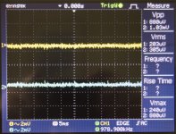
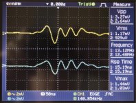
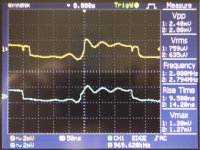
I had actually taken additional pics at 1 & 5ms and 50ns which are attached. Scope averaged at 256, probes X1, inputs shorted at RCA plugs as usual.
Note the difference in vertical scales though.
All pictures with a single earth to the perforated inner plate, as previously explained, which is bolted to the main chassis/case at 6 points with metal standoffs thus also grounding the chassis/case.
The 1ms (caps) and 5ms (no caps) were taken when I was checking for 50/100 Hz AC. Can't remember why I swapped from 1ms to 5ms though.
Those at 50ns because it was the only 'errant' waveform I could find across the frequency spectrum when no RCA caps were attached.
BTW, the 'hump' at 100Hz is 17.8V vs 17.3V at 1Khz with 1V RMS input.
If you want me to run with other time bases please just let me know.
Off to get a glass of wine.
Cheers,
Tony
Attachments

You have some noise issues Tony and we need to find out where its coming from. The metal shrouded IEC inlets often have X and Y caps internally - do you have a spec sheet for yours?
Just pulled out the Schaffner IEC filter socket and used the 'plain Jane' IEC socket.
No change in the scopes at 1ms and 25us with the RCA caps, so it's not the IEC socket I fear. 🙁
Tony, that inlet you are using looks like it has caps across the L and N and also from L and N to earth. I do not understand the Resistance part of the spec. What I would suggest you do for now is use a plain IEC inlet. Unless we have a good handle on the noise where you are, we will be chasing our tail. I think your RFI caps have been causing problems with the IEC inlet The noise you are showing in your scope traces below will not be solved with the RFI caps - they work at frequencies in the MHz range and only work on common mode RFI problems.
For the time base, set it up so you have half a second across the display. That way we can see what frequency components are at play before zooming in.
Re your HF tests - as mentioned earlier, 300 or 400 kHZ is a seriously brutal test on any amp. I would not read anything into that. A more realistic test is a square wave at say 20 or 30 kHz. This will have HF components and will soon tell you if you have response anomalies which you will see as excessive overshoot - but keep in mind that the TPC comp scheme used on the kx-Amp will give you some small overshoot.
Get a load on this thing, do a 2.8 V pk-pk square wave test and if all looks good, check your offsets and play some music through it.
We can then also see if you have any hum etc.
Tony, connect a load. You need to take the plunge.
🙂
Will do, didn't find a difference before though (with no input)
Dummy load is 2 sets of 8.2 ohm 50W Arcol W/W resistors in parallel connected in series giving 4 ohms (half way) and 8.2 Ohms between both ends.
Problem is these resistors are not 'non-inductive' and have an inductance of around 4mH each. Not sure that this might be a problem.
Other problem is I only have one set so can only check one channel at a time.
Tony, that inlet you are using looks like it has caps across the L and N and also from L and N to earth. I do not understand the Resistance part of the spec. What I would suggest you do for now is use a plain IEC inlet. Unless we have a good handle on the noise where you are, we will be chasing our tail. I think your RFI caps have been causing problems with the IEC inlet
As mentioned above, checked with a plain IEC inlet a few minutes back and it made no difference to the previous scope images at 1ms and 25us. Almost precisely the same as with the filtered IEC socket.
Do you suggest I still use the 'plain Jane' IEC socket anyway for now?
I’d stick with the plain IEC inlet.
Those load resistors are very inductive - you are going to get ringing and stuff if you use them.
Suggest you just go straight to speakers. Do you have any other low value resistors around?
Those load resistors are very inductive - you are going to get ringing and stuff if you use them.
Suggest you just go straight to speakers. Do you have any other low value resistors around?
I will try to post up the dual mono wiring scheme later tonight. I’m about half way. It’s the one scheme where I think you will need ground lifters.
I’d stick with the plain IEC inlet.
Those load resistors are very inductive - you are going to get ringing and stuff if you use them.
Suggest you just go straight to speakers. Do you have any other low value resistors around?
Only resistors I have > 1/2 W are around 5W - but they're also wire wound. Not sure of their inductance.
Quick Note:
This morning I tried running the 2 amps from the same Ripple Eater using the RFI filter IEC and 'plain Jane' one. I pulled the fuses on the second RE (they're individually fused + & - lines) so it was 'inactive' although still coupled to the common '0V' transformer secondary.
Unfortunately made no difference. These errant waveforms still persist with the RCA caps in place.
I'll do some more work and see what I can find out.
Cheers
It's all in the case (so it appears).
The case/chassis (Modushop 4U) was set up with an internal perforated base from the same company.
The perforated plate, on which the surge regulator, transformer, and fuses are mounted is attached to the main chassis at 4 points using metal standoffs.
The mains earth was attached to the perforated plate whilst the 4 standoffs were used to earth the case via the perforated plate.
The Amps are connected, one per side, to the heatsinks whilst the 2 Ripple Eaters, one per amp, attached internally to the front, 10mm thick, front panel.
This setup gave multiple problems when the 2 RCA 2.2nF were earthed either at the chassis as I've previously reported.
A complication to this scheme was that the Schaffner IEC plug used has a metal case. Thus it was earthing both on the rear chassis panel punched 'hole', and via the direct connection from the 6.35 mm plug on the IEC connector to the perforated inner plate.
Thinking this 'double earth' might have caused the problems I used black electrical tape to isolate the IEC socket case from the rear panel making only the main IEC earth connection the 'active' one connected to the perforated plate. The chassis/Case is still earthed by the metal standoffs.
Unfortunately this made no difference.
This morning I removed the metal standoffs from the perforated plate and installed nylon ones - thus completely isolating the chassis from the perforated plate. The IEC socket case was still isolated from the chassis by virtue of the electrical tape around the metal case. In other words, the chassis/case was not grounded.
Connecting the 2 RCA 2.2nF caps between the RCA grounds and the chassis/case (no earth to chassis) worked very well. 😀
As above and adding a single earth wire from the perforated plate to the chassis gave almost identical results (as per 'scope'). Maybe marginally worse with a very small difference in noise. This is the preferred method as the case must be earthed for safety reasons.
Connecting the caps to the perforated plate gave the worse results - but still significantly better than what I had been getting. Mostly there's more noise with this schema and a very small amount of 'oscillation' at 25us as compared to the above two (one can see the 'oscillation envelope' but it's in the uV region rather than mV as previously)
Ultimately it seems that the 4 metal standoffs at each corner of the perforated plate were creating some form of earth loop within the case. Perhaps the experts can explain why.
BTW Bonsai, I attached my 8.2 Ohm dummy load to 'Channel 'A' and if anything it's slightly better than Channel 'B with no load attached.
Next is to do some 'permanent' attachments of the earth RCA caps and see if the performance is even better.
In all cases above the 256 averaged scope readings at 1&5 ms and 25us were < 200 uV mostly less than 100uV.
Metal standoffs used were 15mm, nylon ones 12mm. If they were the same I would have used just one metal standoff for the perforated base/chassis/case earthing.
As it is I'll use a separate wire (which would probably give a more sound chassis earth anyway.
Hope this helps others.
Great news on your progress Tony. I’ll have to think about the chassis earth loop thing a bit. Could it be they were not making good connection with the chassis? IIRC they are zinc plated.
Good news about the load resistor working. You may get some ringing using it on a square wave test, but this would be expected and completely normal.
As a general comment, you should always have one and only one connection to the chassis. I see there is a earth/ground connection point on the Schaffner socket, so if you use this socket, you should make the connection on the Schaffner your single ground point (and remove the insulation you have put on it)
The reason why you have one and only one earth/grounding point is that the mag fields from the transformer(s), or any cables carrying heavy AC current, always couple into the metal work* and cause currents to flow around the chassis. If you have two bond points, there will be an AC voltage between them and this can cause a noise loop.
*the mag field always takes the path of least reluctance which is why when you put the lid on the amplifier, hum/noise often drops a few dB.
Last edited:
Great news on your progress Tony. I’ll have to think about the chassis earth loop thing a bit. Could it be they were not making good connection with the chassis? IIRC they are zinc plated.
Good news about the load resistor working. You may get some ringing using it on a square wave test, but this would be expected and completely normal.
As a general comment, you should always have one and only one connection to the chassis. I see there is a earth/ground connection point on the Schaffner socket, so if you use this socket, you should make the connection on the Schaffner your single ground point (and remove the insulation you have put on it)
The reason why you have one and only one earth/grounding point is that the mag fields from the transformer(s), or any cables carrying heavy AC current, always couple into the metal work* and cause currents to flow around the chassis. If you have two bond points, there will be an AC voltage between them and this can cause a noise loop.
*the mag field always takes the path of least reluctance which is why when you put the lid on the amplifier, hum/noise often drops a few dB.
Yes I'm feeling better about the whole setup now.
As regards the standoffs, have had them in my toolbox for some time. They may be zinc coated, not sure, but I did measure resistance from perforated base and chassis and essentially got 0 ohms so I doubt there was a conductivity issue.
I think that earth loops were the problem - can't think of anything else at this stage.
The proof of the pudding will be when I finalise the construction and run a separate earth wire permanent connection (ditto the RCA caps). Ill let the forum know.
I'm using the Schaffner earth 'tab' for the ground, not the earthed 'casing'. The casing is insulated from the chassis by virtue of the electrical tape because the casing itself doesn't make a consistent contact.
I had used the case ground in the original setup to isolate the Schaffner main (tab) ground only to try it as a 'single ground' as an experiment.
I'll not purchase a similar item again where there's a possibility of 2 earths existing - nor a 'push in' socket (better to have one bolted to the chassis). Also better a plastic case on the IEC with a single earth tab.
We live and learn.
Tony,
Tony,
Thanks for sharing your result, but I am somewhat confused.
Many of us diy’ers use the perforated base plate with the Modushop series of enclosures. I am confused by what you mean by what 4 points you are discussing with regards to “standoffs.”
That’s not what I have. The baseplate is attached to the bottom heatsink brackets using 4 screws and 4 nuts. Is that different in your setup?
Can you share a detailed photo including the “nylon standoffs”?
You did share a previous photo in post #803.
Best,
Anand.
The perforated plate, on which the surge regulator, transformer, and fuses are mounted is attached to the main chassis at 4 points using metal standoffs.
This morning I removed the metal standoffs from the perforated plate and installed nylon ones - thus completely isolating the chassis from the perforated plate.
Tony,
Thanks for sharing your result, but I am somewhat confused.
Many of us diy’ers use the perforated base plate with the Modushop series of enclosures. I am confused by what you mean by what 4 points you are discussing with regards to “standoffs.”
That’s not what I have. The baseplate is attached to the bottom heatsink brackets using 4 screws and 4 nuts. Is that different in your setup?
Can you share a detailed photo including the “nylon standoffs”?
You did share a previous photo in post #803.
Best,
Anand.
Hi Anand,
Basically the same thing, just replacing the 4 screws with standoffs.
It provides some space between the perforated plate and the bottom plate of the amplifier so that one can, for example, run the power cable to a front panel on/off switch from the rear. Someone suggested it on one of the DIY forums here so I thought it was a good idea.
I haven't tried screwing the perforated panel (PP) directly. Does the PP also make direct contact with the chassis along its length if screwed on directly?
In my setup the PP 'floats' over the main chassis/case with the only contact being via the 4 metal standoffs. Which is why I think maybe the configuration is allowing multiple earth loops?
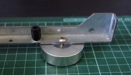
Attached is a picture of a 12mm nylon standoff attached to the chassis. I had posted it on the DIY Audio Store Chassis forum to demonstrate how I was using the 4 corner base plate screw points to attach the metal feet I was using (The screw holes are tapped, bolts added and the threaded feet screwed in from the bottom. The feet hold the corners of the base plate in position along with the two central bases plate screws).
Hope this clarifies the situation.
Basically the same thing, just replacing the 4 screws with standoffs.
It provides some space between the perforated plate and the bottom plate of the amplifier so that one can, for example, run the power cable to a front panel on/off switch from the rear. Someone suggested it on one of the DIY forums here so I thought it was a good idea.
I haven't tried screwing the perforated panel (PP) directly. Does the PP also make direct contact with the chassis along its length if screwed on directly?
In my setup the PP 'floats' over the main chassis/case with the only contact being via the 4 metal standoffs. Which is why I think maybe the configuration is allowing multiple earth loops?
Attached is a picture of a 12mm nylon standoff attached to the chassis. I had posted it on the DIY Audio Store Chassis forum to demonstrate how I was using the 4 corner base plate screw points to attach the metal feet I was using (The screw holes are tapped, bolts added and the threaded feet screwed in from the bottom. The feet hold the corners of the base plate in position along with the two central bases plate screws).
Hope this clarifies the situation.
Attachments
Could be that the connection between the base plate and the rest of the chassis was not good due to the zinc plating. However, if you you wire with just a single chassis bond point, there should not be any noise loops.
This is an interesting problem that’s for sure!
This is an interesting problem that’s for sure!
Tony,
Thanks for clarifying with the picture. Indeed that's a unique method although it seems that it may introduce the possibility of a ground loop as you had experienced.
Where you have the nylon standoff is where a screw/nut combination is used (4 of them) to attach the baseplate (perforated panel) to the bottom bracket of the heatsinks.
In practice, I have never had your issue although I admit it may not be as aesthetically pleasing.
That being said, it is peculiar, as I would not expect your method of mount would make a poor ground connection (even though your DMM says otherwise!).
Best,
Anand.
- Home
- Amplifiers
- Solid State
- Hifisonix kx-Amplifier