Thank you very much!
Thank you very much! That was indeed the issue. I have a RME ADI-2 pro FS ,that i thought would take +24dBu = 12 Volt RMS on the Input (I even chose this reference level in the menu), but obviously doesn´t.
With a ten times divider I get 0,1% THD at 6 Volts and 0,9% THD at 13 Volts. Still a little high, but I can go further from here.
Thanks again allmighty Zen Mod and BDP for your kind support.
higher Distortion due to JFET/Mosfet or too dumb to measure?
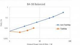
Whilst building my second BA-3B monoblock I did some more distortion measurements on the Gainstage and found roughly the same result as before:
In stereo mode I measure 4 times the distortion as Papa did (0.02 % vs 0.005% at 2.8 Volts). In balanced mode my amps perform almost exactly as Papas did in stereo mode. 2nd order harmonic was nulled via P3 and this is only 3rd order.
In stereo THD measurements were made with RME soundcard and Keithley 2015 DMM and results were the same. As all 4 channels are more or less the same I guess that these results are real.
Now where does the difference come from? Is it because I used neither Toshiba JFets nor Toshiba Mosfets? Or am I not supposed to poke around with unshielded probes for THD measurements? The JFets I used are linear systems from the shop and were really matched within 0,1 mA.
I already love the amps, but if I can make them even better with Toshiba parts, I would do that especially as I have spare PCBs for the Gainstages.
Any advice is highly appreciated.
Attachments

Many thanks again omniscient Zen Mod. To match those Mosfets N to P I used "odd" ones out of the normal range of Vgs. So I will try to solder in some sockets and test some more mosfets in the normal range before ordering Toshiba parts.
What an awesome forum full of kind people this is
What an awesome forum full of kind people this is
I built the first FE with Toshiba parts and lo and behold it performs as expected. Turns out I am an H2 guy - so I have to dial it in balanced mode. To get control over the phase of H2 I built a balanced Hall - notch filter as published by Mr Kuhn.
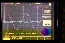
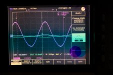
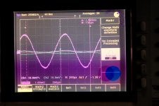
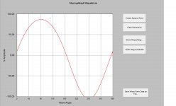
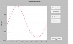
My filter is not steep enough so I can only see small portions of H2 in the mixed signal. With the help of a nice sinwave calculator found on this forum, I simulated positive and negative phase H2 and it shows as exaggerated negative (neg. H2) or positive (pos. H2) peaks of the fundamental sinewave. ("positive H2" = -90° phaseshift of H2, "negative H2" = +90° phaseshift of H2)
When I turn P3 counterclockwise I get a slight shift up (possibly meaning positive H2) and when I turn P3 clockwise I get a slight shift down (possibly meaning negative H2). This is the same for both the positive and negative signal.
Where I get mixed up is which phase was favoured by most people - sometimes I read neg. sometimes pos. in the publications. Of course I can try and probably will test both ways. (Also the filter has a phase shift around 135° or so at fundamental and around 90° at H2 which might mess up things further. Also I have only 2 channel oszi and not enough x1 probes)
Does that "phase-measuring" make any sense and which phase should I go for (0,02 neg. H2 at 2.8 Volts maybe)? Is there a better way to measure the phase of H2 in a balanced signal - can Arta do that?
Thank you very much
Attachments
-
 phase shift.JPG343.4 KB · Views: 200
 -
 P3 clockwise .JPG342 KB · Views: 182
 -
 P3 counterclockwise.JPG269.5 KB · Views: 191
 -
 H2 nulled.JPG265.2 KB · Views: 174
 -
 negative H2.jpg185.9 KB · Views: 169
 -
 positive H2.jpg200.1 KB · Views: 205
 -
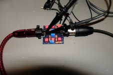 balanced hall filter.JPG317.2 KB · Views: 245
 -
 Toshiba FE.JPG370.6 KB · Views: 232
 -
 THD balanced.jpg164.9 KB · Views: 352
I read the BA3 article once more and it seems to coincide.
Turning the wiper (lowering the resistance) of P3 towards Q1 (counterclockwise) on the positive signal half gives rise to positive H2. And as the negative half is mirrored on the pcb and then again mirrored on the screen/speaker, turning the same direction (counterclockwise) gives the same result in the differential signal for both halfes.
As this is the newest and more detailed source I will go for neg. H2.
Pass H2 Harmonic Generator - Positive Feedback
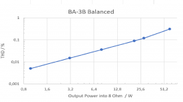
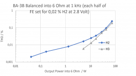
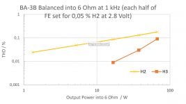
I settled for 0,05% neg. H2 for each half @ 2.8 Volts = 5.6 Volts balanced.
Attached are some THD measurements into 6 Ohms at different setting for P3.
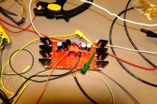
This is with Toshiba Jfets and Mosfets. Output stage has 6 pairs of IR Mosfets per half.
I can only compare to a crappy built F5 turbo V1, Luxman M-383 and AV Denon 5803. It beats any of those with ease. Percussions, Guitars, vocals, overall clarity are insane. Center image and soundstage have also improved. Never was I able to "touch the music" like this.
Only thing negative are a few annoying hi-hats, when listening off center, that get muffled or smeared with my other amps (except F5 of course).
Cheerio
Attached are some THD measurements into 6 Ohms at different setting for P3.
This is with Toshiba Jfets and Mosfets. Output stage has 6 pairs of IR Mosfets per half.
I can only compare to a crappy built F5 turbo V1, Luxman M-383 and AV Denon 5803. It beats any of those with ease. Percussions, Guitars, vocals, overall clarity are insane. Center image and soundstage have also improved. Never was I able to "touch the music" like this.
Only thing negative are a few annoying hi-hats, when listening off center, that get muffled or smeared with my other amps (except F5 of course).
Cheerio
Attachments
Thank you also for the DIP switch boards 😉
I felt like the information was missing in the threads.
I did bias the FE at 100mA and the output at 0,4A each.
Now I´m eagerly waiting for ZMs Iron Pumpkin to be able to listen to DSD direct. The preamps I have at hand just degrade the sound too much.
I felt like the information was missing in the threads.
I did bias the FE at 100mA and the output at 0,4A each.
Now I´m eagerly waiting for ZMs Iron Pumpkin to be able to listen to DSD direct. The preamps I have at hand just degrade the sound too much.
And thank you also for working with me on the DIP boards. Also, I can't remember if I had publicly thanked Flocchini yet for sending me the initial information. If not, thank you, Bob!
I truly appreciate your graphs and set-up information. One of the things I had been considering is how to set relative H2 and H3 when going balanced. So, now I know that it's achievable.
I currently have my FE at 100mA. Before taking the big plunge to building the other amp and going balanced, I am waiting to switch to Toshibas, install bigger heatsinks, and thermally couple Q3 and Q4.
My OS is currently set at ~0A44 per device with 24V rails. Dissipation per side is ~125W. I may back off just a bit. The heatsinks are showing ~54C in 22C ambient measured with an IR thermometer and a K-probe with a DMM. That tracks well with the data Gianluca published. To me, the heatsinks are too hot. I must be a wimp. I may get 5U/500 for these beasts or get some fans 😀
Your amps with an Iron Pumpkin should be an incredible pairing. 🙂 I have been waiting to get a kit from ZM. I have the balanced Iron Pre as my main pre-amp, and I absolutely love it. However, like many DIYers, I've been lusting after the Iron Pumpkin.
Regarding H2: yes just take care to invoke negative H2 (wiper towards Q2) on the postive signal half and positive H2 (wiper towards Q1) on the negative signal half - that way they add up to negative H2 in balanced operation
Regarding heat: I have my amps vertically atm and did install 2 140mm fans inside on the top plate to help a bit. Had to rotate the upper cover so the slits were to the front (no space above FE due to sinks and caps). Did a crappy job on drilling bigger holes on the top cover as the mounting holes do not line up rotated. Also I installed a emergency thermostat to cut power at 68°C and turn on the fans at 60°C
053GAB155A-140Y Sensata Technologies | Mouser Deutschland
67F060 AIRPAX | Mouser Deutschland
Yess ZMs Pre looks so sweet
take care
Last edited:
Regarding H2: yes just take care to invoke negative H2 (wiper towards Q2) on the postive signal half and positive H2 (wiper towards Q1) on the negative signal half - that way they add up to negative H2 in balanced operation
Beautifully explained. Thank you.
Regarding heat: Also I installed a emergency thermistor to cut power at 68°C and turn on the fans at 60°C


 You have fully embraced the concept of a Burning Amp!
 Me: My heatsinks are at 54C. My delicate skin!
You: Well, I did use a few 140mm fans, but they only kick on if the sinks get to 60C.
Me: <Hangs head in shame> - I'm not worthy.

In all seriousness for anyone out there... 54C is perfectly described on the Papa scale. I can hold my palms on for a good while, but it's definitely hot. I can easily see why 2s was chosen. Any hotter, and I'd be reaching for the aloe.
Ozo is clearly the more mature constructor. 😀
Papa's Heat Scale #1858

Only thing mature about me is my age on my passport 😀
I´m just enjoying the light-heartedness of a bloody beginner who has never smoked an amp yet 😉
Also I have enough Mosfets left for replacement 😎
After tuning my speakers capacitors with nice results I wondered, if I can tune my BA-3B amps in a similiar fashion.
Thought of 400 uF Films for the PSU rails:
DCP4G064009JD4KSSD WIMA | Mouser Deutschland
and some bypass caps for the FE 10uF coupling caps:
JDM-Cu-230: 0.33uF 600Vdc Duelund JDM Pure Copper Foil Capacitor | Hifi Collective
After all Papa used some film on his BA1 prototypes PSU. Anything to be gained or a waste of money and time?
Thank you
Last edited:
I've searched the thread but not found the answer to an obvious question: Are there boards for this? or Gerbers I can use to get boards made? Or is there a simple way to wire two BA-3 boards together to make them balanced?
Richard,I've searched the thread but not found the answer to an obvious question: Are there boards for this? or Gerbers I can use to get boards made? Or is there a simple way to wire two BA-3 boards together to make them balanced?
The first post of this thread has a schematic published by NP that shows how the R5 source resistors (that are 100 ohms in the BA-3 board) are combined together to make 200 ohms instead of going to ground.
So in essence, since each BA-3 board is a STEREO/2ch board, you need to have TWO BA-3 boards in order to make this a balanced design and implement what NP has shown.
Hope that clears it up. Of course matching all transistors, resistors, etc...will only help.
Best,
Anand.
Anand is correct - one front-end board and two output boards, will make one balanced channel.
Which means each channel monoblock is the equivalent thermal load to a standard stereo amp.
Which means each channel monoblock is the equivalent thermal load to a standard stereo amp.
Richard, you've posted in both the pre-amp thread and this thread. Are you wanting to build a speaker amp and/or a pre-amp?
Either way, the link to the boards is here. You need two of these for a balanced pre-amp as Anand mentioned.
https://diyaudiostore.com/collections/pre-amplifier/products/burning-amplifier-gain-stage-for-ba-3
See some previous posts for a (fairly) simple way to switch back and forth from stereo to balanced.
If you want to build a speaker amp, you'll need a set of output stage boards also. These are an excellent choice. When paired with those FE boards, you get a BA-3 amplifier. Yeah, I know. It confused me too.
https://diyaudiostore.com/collections/power-amplifier/products/burning-amplifier-complementary
Have fun!
- Home
- Amplifiers
- Pass Labs
- Burning Amp BA-3b (Balanced)