wiper of P1 need to be shorted to GND
wiper of P2 shorted to neg rail
input grounded, no load on output
PSU tested, same as proper connection of rails to channel pcbs
best to have 2 DVMs, connected as per BIAS and DC Offset procedures from post #1
at start, do one channel at a time - meaning - just first one connected to PSU while setting it
when done biasing up to 70%, power off, connect second channel , power on and do the same as with first channel(first channel being connected because it is pre-set)
when having both pre-set to 70% if Iq, proceed with final biasing of both channels
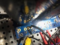
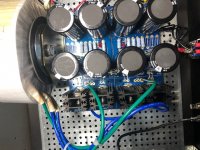
Red is wrong in first pic, that is input. You should have v+ and v- to each amp board. Double check with first few pages of this thread.
^ - My guess is they're describing the wiring in the pic on the right vs. the input wiring on the left.
F6 - Further Updates
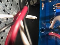
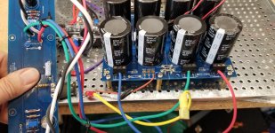
Here are more pictures - after the change to teh power supply I fired up unlike before (when it was connected wrong) the bulb just dimmed slightly and remained on -- before it faded to off -- bias was about .6 and measuring across the speaker terminals was about 2 volts - the led lit no smok e- but I might still have a fried resistor.
my wires are a tangle but I showes the black and red in the trio coneected to the board and where they come from on the power supply.
I don't think I'm ready for a speaker
Attachments
Red is wrong in first pic, that is input. You should have v+ and v- to each amp board. Double check with first few pages of this thread.
I'm using red as positive in [IN1] from signal input. Black as ground. You are saying I have them reversed? Plus should go into AG-1?
wiper of P1 need to be shorted to GND
Sorry. I described green incorrectly: it is negative ground from PSU. White [+] and Black[-] are out to speaker terminals.
wiper of P2 shorted to neg rail
input grounded, no load on output
PSU tested, same as proper connection of rails to channel pcbs
best to have 2 DVMs, connected as per BIAS and DC Offset procedures from post #1
Yes. I had them in position. But resistor went first.
at start, do one channel at a time - meaning - just first one connected to PSU while setting it
I'm only working on channel B at this point. Haven't assembled the other one yet. For good reason.
when done biasing up to 70%, power off, connect second channel , power on and do the same as with first channel(first channel being connected because it is pre-set)
when having both pre-set to 70% if Iq, proceed with final biasing of both channels
thanks for your assistance.
I'm using red as positive in [IN1] from signal input. Black as ground. You are saying I have them reversed? Plus should go into AG-1?
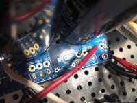
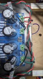
If that red goes to rca input that's correct. What I am wondering about is your connections from power supply board to amp boards. Attached is another pic of my amp, red is v+, green is v-, black is ground, purple is shield wire from Antek.
Attachments
Passed the power supply dim bulb test and wired in the left side board amp board. But before a power up test, I decided to turn the 25 turn trim pots to half setting. Started with the bias pot.
Haven't used this type of pot before. They don't seem to have a limit stop. If that's the case, I'm not sure where the setting is now after a lot of clockwise twisting.
Any thoughts would be appreciated.
Haven't used this type of pot before. They don't seem to have a limit stop. If that's the case, I'm not sure where the setting is now after a lot of clockwise twisting.
Any thoughts would be appreciated.
I start counting and when I got to around 12ish I usually hear a click. Not very loud so listen for it.
I start counting and when I got to around 12ish I usually hear a click. Not very loud so listen for it.
there is one special tool which can help ...... I mean - to avoid wild guessessssss
that tool is called DMM
set it to Ohms , find appropriate points to put probes, then set trimpot as advised
if help is needed for appropriate points , simple cry for help here is usually enough
I know, cried zillion of times

Thanks.
So I still can't figure out why the R4 resistor blew?
in case that mosfet is fully opened ( be it P or N) , you have permanent full rail voltage across NFB chain, in which case dissipation across 18R is aroundish 600mW
enough to toast it......... maybe not to kill it but certainly enough to ruin beauty coating
in which case is best to replace it - you never know when in future ( even if measures correctly) resistor could decide that what's enough is enough ......
ChipTech, Mighty ZM,
Before the dump question, I was thinking I would need to dismount the board to set the pot with my DMM. Well, ZM, you forced me to think and find the locations on the front of the board where I could do the dam thing. What a moron. Anyway, thank you both.
Regards, Bill
Before the dump question, I was thinking I would need to dismount the board to set the pot with my DMM. Well, ZM, you forced me to think and find the locations on the front of the board where I could do the dam thing. What a moron. Anyway, thank you both.
Regards, Bill
when you realize that you're moron, there is start of unspoiled happiness and prosperity
no obstacles in feeling bad because you don't know something , just realization and then learning it in best way possible
I'm happy all the time
P1 - one leg of R9 and wherever you can touch GND easily; DMM will tell you which side of R9 is proper one (if you see 10K+ , take other leg of R9)
P2 - one leg of R10 and wherever you can touch neg rail easily; DMM will tell you which side of R10 is proper one (if you see 10K+, take other leg of R10)
when you realize that you're moron, there is start of unspoiled happiness and prosperity
no obstacles in feeling bad because you don't know something , just realization and then learning it in best way possible
I'm happy all the time
P1 - one leg of R9 and wherever you can touch GND easily; DMM will tell you which side of R9 is proper one (if you see 10K+ , take other leg of R9)
P2 - one leg of R10 and wherever you can touch neg rail easily; DMM will tell you which side of R10 is proper one (if you see 10K+, take other leg of R10)
From post #1: Power Up "If you start with the pot in it’s default position, it will most likely have too much bias initially. Turn off the power, turn down P2, and try again." That didn't sink in.
I tested the R9 resistor and it still works. I replaced it.
I now think I understand that while I thought I had both trimpots in the "middle position'" but both were set too high. So how to set trimpots at start?
Using your guidance I measured the pots and made adjustments:
P1 measures 1.98K high and 82.9 ohms in the low position.
P2 measures 10.15K high and 131.0 ohms in the low position, using your directions.
I'm assuming that 82.9 and 131.0 ohms are viable targets to use.
Net, net, if startup bias target is 500mV, set trimpots below that target.
If I get this, since we want 500mV to start, both trimpots should be set below that target.
If this is correct, I'm a little better educated. If not, I'll need further guidance.
More f6 debugging
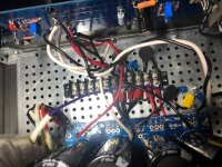
I redid my power suply in accordance witht the picture posted by @mlwebb. I measured voltage from ground to both negative and positive out and it was 13.8 and -13.8 volts -
I have seen some posts mentioning 25 volts so I'm a little concerned
My bulb dims but not substantially - my offset is around 2.2 volts -- adjusting the offset does lower it - I got it from 3.8 down to 2.2 volts but I doubt I'll be able to get it down where it should be
the heat sinks do gradually warm
My thinking is that my wiring is ok but I have a problem from whatever I fried when I saw smoke earlier -- I did some research and I undersand that I can't really measured the resistors in circuit and I assume I can't measure anything else without removing it
Should I start pulling parts and then testing them?
Or is there something else to look for?
Are there points in the circuit where I can check voltage and narrow down my problem?
Sorry if this is newby stuff
Tom,
If you need help, I wouldn't mind giving you a phone call, I am local to you. You can pm me with your phone number if you would like.
See my post #3286. I don't think you have the correct green/blue pairings from the Antek toroid. Your V+/V- rails are around 1/2 of what I would expect, which is +/-26 to +/- 28 volts.
Thanks,
Anand.
Last edited:
- Home
- Amplifiers
- Pass Labs
- F6 Illustrated Build Guide