The PSU is definitely not connected correctly. I would recommend disconnecting the amp board from the PSU first and then figure out the proper connections and get the PSU working by itself first.
Do not power it back on again the way it is now.
Do not power it back on again the way it is now.
F6 Follow up
I have posted more pictures --
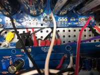
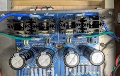
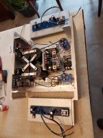
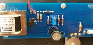
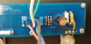
I took the board out and tried to lay it on its side beside the power supply to show better - the other channel isn't wired yet.
With the black and white wires the white wire connected to out goes to the speaker output and the black wire that is a double connected with a white wire a little higher up is also connected to the other speaker out - which I am thinking doesn't seem right - that is putting 14 volts straight into the terminal.
I have posted more pictures --
I took the board out and tried to lay it on its side beside the power supply to show better - the other channel isn't wired yet.
With the black and white wires the white wire connected to out goes to the speaker output and the black wire that is a double connected with a white wire a little higher up is also connected to the other speaker out - which I am thinking doesn't seem right - that is putting 14 volts straight into the terminal.
Attachments
OK I started with DC Offset that I determined was to connect the multimeter to the outputs - from what I read it should be zero - I got 14 volts -- I don't think that is good.
My power supply is about 14volts - So I am thinking a short
I agree with twitchie.
See this link and scroll down to 6L6's picture where he has the transformer secondaries connected to the monolithic bridge rectifiers:
diyAudio Power Supply Circuit Board v3 illustrated build guide
Also, look at the Antek AS-3220 diagram on this link (it's similar to your AS-4220 from a wire connection standpoint):
AS-3220 - 300VA 20V Transformer - AnTek Products Corp
https://www.antekinc.com/content/AS-3220.pdf
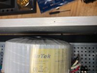
Notice that with Antek dual secondaries, that a green wire is contiguous/continuous with a blue wire. You need to pull out your DMM and make sure you know which green has continuity with which blue wire. The resistance between one green and one blue wire will be close to zero ohm. Make sure you keep those two together (and twist them well to minimize stray magnetic fields). The resistance between another green and another blue wire will be close to zero ohm. Make sure you keep that pair together. Each pair then connects to their respective AC inputs on the rectifier board.
Other transformer manufacturers, for example Plitron as 6L6 used in his build (link above) have different colors for all 4 secondaries so it is difficult to connect them in a short circuit.
I am a little concerned that you may have done so.
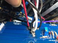
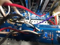
You also seem to have (2) blue and (1) green wire connected to one board while you have only (1) green wire connected on the other board. That is wrong.
Best,
Anand.
Last edited:
The blue wire of one of the secondary windings is going to the wrong place. Seems like it is going to ground on the one cap section and not to the input on the diode bridge.
Last edited:
Thanks, that picture totally clarifies it - I was totally screwed up but somehow I measeured it and 14 volts was coming out of the power supply - I think I'll go back hook it up right dosconnect the board I had connected measure the power supply then reconnect and see what happens.
Some news about an other Nelson Pass F6 whitch raised to life few month ago, but started beginning 2020.
It's the first solid state amplifier I made, more trained to build valve amplifier like ARC D79, PP Ampex 60W, PP GEC KT88, 2A3 and 2A3JJ40 mono triode etc...
Power supply and filtering was planed for an Hiraga 30w classe A. On the way I changed my mind and I switch from Hiraga amplifier to the Nelson Pass but I kept the PS.
The transformer is a double C comming from Dissident Audio, the DB226 2x18V 6A.
The filtering is CLC type with hammond choke and a total of 1.2 Farad (2x600.000uf).
I add several modules bought on the net, a soft start module and 2 HP protection module.
I set the bias after one hour running at 0.604v and the ofset at 0.002v.
Amplifier cold, the bias after 2 minutes is 0.540v it goes very slowly to the set value.
The gain factor is between 5 and 6, depending input value:input (BF gene) -->Output (vpp on scope)-->x ampl factor
0.28v--> 1.60vpp-->x5.59
2.84v--> 15.9vpp-->x5.59
5.65v--> 30.2vpp-->x5.54
Clipping on sinus wave at input 7.65v-->42.4vpp on the scope and 14.51vac on 8 ohms load.
Of course I prefer my valves amplifiers, but honestly I must recognize its a fine and energised amplifier plus easy to build.
Many thanks to 6L6 for it's advices and also many others...


Hey I also finished my F6 build!
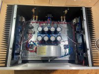
Bit more of a standard F6 build using many of the parts from the site's store.
17 LEDs in this amp! Replaced each Zener with three green LEDs (LTL 4231N) fed by a 3K3 resistor.
22KuF caps in the PSU. Added a 0.1uF ceramic on the output of each rail. Antek 400VA transformer.
Bias is holding steady at 0.5V +/- 5% with the offset <20mV. This is with about 10 hours of burn in time. Going to enjoy the amp the next week then pull open the hood and check measurements again.
Very impressed with the floor noise on this design, hardly any noise at all!
Attachments
Sdfrance, chrism91.....very nice builds! I’m curious what temperature your getting on the outputs? Thanks
Hi Monk55,
Me also, that is why this morning I order for a laser thermometer, I will get it in10 days . regards. Serge
Me also, that is why this morning I order for a laser thermometer, I will get it in10 days . regards. Serge
Sdfrance, chrism91.....very nice builds! I’m curious what temperature your getting on the outputs? Thanks
Thanks!
I was getting 52-53C measured with my Fluke 179 after a few hours running at 0.5V +/- 5% with the offset <20mV. Below 55C so I am happy 🙂
Will have to test this again in a week or so after a bit more time with the amp.
ChrisM91,
Very clean build, I appreciate that!
I can't clearly see if you have the IEC ground tab connected to chassis ground. Just making sure you are safe.
Best,
Anand.
Very clean build, I appreciate that!
I can't clearly see if you have the IEC ground tab connected to chassis ground. Just making sure you are safe.
Best,
Anand.
Thanks Anand!
Yes, the IEC ground has its own dedicated ground lug on the chassis. The other chassis ground point has two lugs, one for the transformer shield and the CL-60 (audio ground).
Yes, the IEC ground has its own dedicated ground lug on the chassis. The other chassis ground point has two lugs, one for the transformer shield and the CL-60 (audio ground).
Thanks Anand!
Yes, the IEC ground has its own dedicated ground lug on the chassis. The other chassis ground point has two lugs, one for the transformer shield and the CL-60 (audio ground).
Okay, I see it now. The green wire from your IEC terminal comes in, wraps around beneath your PS board and then attaches to chassis ground. Just make sure that you check with your DMM that there is instantaneous continuity between the two washer/screw attachments to the baseplate since they are all not connected together with just one common washer/screw. I can understand why you did it. It's a matter of convenience and neatness 😀.
Best,
Anand.
Hey I also finished my F6 build.
I love seeing new amps born! Congratulations. 🙂
Problem on R4
Hello,
Need a little help. I tested my PSU with the dim bulb.
PSU shows +25.15/-25.1 with a Antek 32-18
I then tested channel B with dim bulb. Passed.
I was starting to adjust the bias with the dim bulb still in place.
And I fried R4. I used a Dale 18 ohm resistor [RN55D 202IJ 18R2F] from the F6 parts kit.
I had checked and have now rechecked continuity at the Mosfets. All good.
I used the 6.8V Zeners and 3.3K resistors.
I had positioned the pots in the middle of their range.
Nothing else looks fried.
I triple checked Q3 and Q4.
Wires: red to V+, blue to V-, black to ground. White is out and green is out ground.
Led works [yeah].
Any help is appreciated.
Attachments
- Home
- Amplifiers
- Pass Labs
- F6 Illustrated Build Guide