🙂
I'm happy with below or better. Others accept a little looser, others try to hit it perfectly.
1. Within 5%
2. <20mV when in steady state.
I'm happy with below or better. Others accept a little looser, others try to hit it perfectly.
1. Within 5%
2. <20mV when in steady state.
Thanks ItsAllInMyHead!
I'll aim for those tolerances then.
I am going to try and leave the amp running for a few hours today while I work to allow for burn in and see how the bias moves.
I'll aim for those tolerances then.
I am going to try and leave the amp running for a few hours today while I work to allow for burn in and see how the bias moves.
What is the input sensitivity of the F6? I know I read it somewhere but I can’t find it now, I want to say ~2.5V 😕
It's in the manual Monk55 linked. But it's important to know why (for newbies; you seasoned veterans know all this stuff and more!):
P = V (squared) / R; where P is power, V is volts RMS, and R is ohms.
25 watts = V(squared) / 8 ohms; solve for V = sqrt (25*8) = 14.14 volts RMS.
You know the gain of the F6 is 14dB.
gain in dB = 20 log (V/V).
So you now solve for the input volts RMS which if increased by a factor of 14dB equals 14.14 V RMS.
14 = 20 log (14.14/V); solve for V and you'll find it is 2.83V RMS.
So 2.83V RMS on the input will clip the amplifier, that is give an output of 14.14V RMS which you know is 25 watts/8 ohms.
The other way to solve it is to recall that 14dB of gain is equal to 5 times of amplification. So you can just take 14.14 V RMS / 5 = 2.83V RMS.
And consequently you can use the same thought process and solve for 1W RMS output which is 2.83V RMS. You'll find that the input sensitivity is then 0.57V RMS approximately.
Best,
Anand.
IRFP250 at Q1 (has to be IRFP250 not IRFP150)
IXTH64N10L2 at Q2
This will get you the sound.
LED Mod + R7/R4 around 3k - Lower noise, better regulation, and adds thermal compensation to the bias circuitry, compared with the stock zener.
Reduce R1 and R2 to 0.22 Ohms (lower if you want) - Not critically important if you have very good resistors, but it does provide some improvement.
Increasing R4 to between 20 Ohms to 23 Ohms - Improves everything a little
Is it ok to use the Vishay IRFP250 hexfet?
IRFP250PBF Vishay Semiconductors | Mouser Australia
I'm ordering from Mouser and they only have this or the Infineon version. Otherwise I'll order from elsewhere
I used the Vishay IRFP250PBF devices in both of my F6 builds and they sound excellent. They did require upping the zeners to 5.6V to get a minimum of 575mV drop across R2 to achieve good sound.
Thanks, good to know.
My question was related to the combo that Pico had tested and recommended to get a certain sound from the F6
My question was related to the combo that Pico had tested and recommended to get a certain sound from the F6
Well, my power supply passed the dim bulb test. I didn't. The LED at R21 didn't light up. Must have inserted it wrong. R21 is good and I get 25.4 V to ground unloaded on both sides of the supply. Might be a bit high. Mains are 123V and change. I'm using a 2x18V Antek.
The boards are assembled on the heatsinks. Should wrap it up by next week. Using the special order 4Ux500mm chassis. A bit cavernous for the F6, but my next build is the BA3 in the second chassis. HeyBill
The boards are assembled on the heatsinks. Should wrap it up by next week. Using the special order 4Ux500mm chassis. A bit cavernous for the F6, but my next build is the BA3 in the second chassis. HeyBill
Not well documented, but mentioned in a few posts. The two LED's do not go the same way as the schematic. One is set to the positive rail and the other to the negative rail. I had to switch one, too.
I posted earlier that when I fired up my F6 - One channel Only smoke came out and I thought it was toast - - I poked around and things seemed OK - so I tried again without replacing anything - my light bulb dimmed and came up but no smoke and the LED didn't light up - I thought I needed to switch the led around so I did- fired it up again and it lit up - I checked the bias and it slowly rose to about 0.420 before any adjustment -- I think I might be up --
What next? -- Do I connect a speaker? - an old one I suppose - Are there other tests or measurements I should do to make sure I'm ok
What next? -- Do I connect a speaker? - an old one I suppose - Are there other tests or measurements I should do to make sure I'm ok
OK I started with DC Offset that I determined was to connect the multimeter to the outputs - from what I read it should be zero - I got 14 volts -- I don't think that is good.
My power supply is about 14volts - So I am thinking a short
My power supply is about 14volts - So I am thinking a short
how can you make F6 with 14 Volts?
I mean , you need two rails, and if you have two rails (+ and -) , if they are just 14 volts, that's too low
I mean , you need two rails, and if you have two rails (+ and -) , if they are just 14 volts, that's too low
I just set up one channel and haven't connected the other -- maybe that is the problem- My power supply was putting out 14 volts but I understood that was a little high but OK.
I assume to rails means both channels so I need to connect both then try again?
I assume to rails means both channels so I need to connect both then try again?
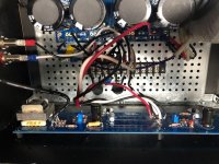
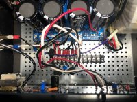
nope; stop whatever you're doing and post pictures
well lit, detailed, so we can deduce how you made it
I can't connect your "14 Volt" figure with anything, except DC Offset on output ...... and you're mentioning "power supply of 14V"
this amplifier is having power supply consisting of two rails , one positive 24Vdc nominally, second negative 24Vdc nominally
nominally means - little lower than that, when amp is fully set and rails are fully loaded
tbrooke,
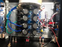
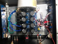
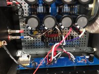
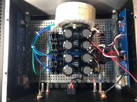
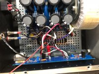
If you can, flip the amp on it’s side and take some nice closeup shots of the actual F6 amp boards. It’s a little difficult to elucidate anything with the bundle of wires on one side of the amp.
Make sure the center bolt of the toroid is not touching the front panel. You don’t want a shorted turn situation.
Have you tested the power supply separately ? Even with 20V secondaries you should be getting +/- 28V or so without a heavy load.
Thanks,
Anand.
Last edited:
- Home
- Amplifiers
- Pass Labs
- F6 Illustrated Build Guide