I tried this - and it looks to me that we just can't place functions referring to param sequences (list) as a SPICE directive.
It must be placed in "Plot Defs File" - right click on the plot -> view -> Plot Defs File.
Add it in there, and save the file.
Then you can add trace with stb() as an expression.
It must be placed in "Plot Defs File" - right click on the plot -> view -> Plot Defs File.
Add it in there, and save the file.
Then you can add trace with stb() as an expression.
I tried that too - no joy.
Error is 'undefined symbol in <<stb>>()'.
It looks like the .func in the plot.defs is not seen.
If you take my .asc and do this, does it work for you?
BTW I routinely use .param and .step on the schematic screen with no issues.
Which make sense as they are sim directives, nothing to do with plotting results.
Jan
Last edited:
Minek is right. It won't work as a .func SPICE directive in the .asc schematic. It will give exactly the error you are getting, I think.
I suspect when you add the function in the "Add Trace" it is giving you the right answer. I believe some people keep the function saved in a text file and copy/paste into the "Add Trace" dialog.
I do not know why it is not working as a function in the plot.defs file. Weird.
I suspect when you add the function in the "Add Trace" it is giving you the right answer. I believe some people keep the function saved in a text file and copy/paste into the "Add Trace" dialog.
I do not know why it is not working as a function in the plot.defs file. Weird.
Bohrok, thanks for posting that. I've been wanting a .measure to read out GM/PM, but I've been to lazy to write and debug it.
Yes that could be the case; plotting the expression works fine.
Still, a riddle why the .func is not 'seen' by the plotter.
I have an uneasy feeling that I inserted it in different plot.defs file than the one the plotter looks in.
I'll explore that further tomorrow.
Jan
Still, a riddle why the .func is not 'seen' by the plotter.
I have an uneasy feeling that I inserted it in different plot.defs file than the one the plotter looks in.
I'll explore that further tomorrow.
Jan
>I do not know why it is not working as a function in the plot.defs file. Weird.
It works for me. I have it my plot defs file, and it works ok.
I think you may need to restart your ltspice after you add it.
It works for me. I have it my plot defs file, and it works ok.
I think you may need to restart your ltspice after you add it.
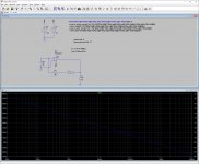
Here is another way to use Tian probe. It also tries to find the gain and phase margins (see View->SPICE Error log).
That looks interesting yes! Will also attack that tomorrow.
Thanks guys so far,
Jan
>I think you may need to restart your ltspice after you add it.
Yes!! So far, so good!
Will try to add Mimek's stuff tomorrow.
Jan
Here is another way to use Tian probe. It also tries to find the gain and phase margins (see View->SPICE Error log).
I got this to run, very nice that it gives the margins!
That is, it reported a plausible phase margin, but the gain margin failed:
Measurement "gain_margin" FAIL'ed
Does it work correctly for you?
Jan
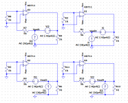
I have a basic question on the configuration of the probes. I see different setups, looking from the circuit to be measured output to the feedback network.
See attached. All 4 setups give exactly the same result. Which makes sense as the measurement sources are AC so there's no difference in 'polarity'.
Am I right?
Jan
See attached. All 4 setups give exactly the same result. Which makes sense as the measurement sources are AC so there's no difference in 'polarity'.
Am I right?
Jan
Attachments
You need to extend the AC analysis to 100MHz. Phase goes to -180 at around 50MHz.
Yes, 100MHz, now it's OK. Thanks for a great tool!
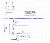
Another issue I found: if I use your method, with the probe subcircuit, the result is an open loop response that drops below 0dB at high frequencies which I guess is realistic.
When I use the method as shown in the attachment, the open loop gain doesn't drop below +27dB, which must be in error.
But I can't find any difference between the two setups.
What am I missing?
Jan
Attachments
Last edited:
No that doesn't change anything. The .step overrules it anyway, and it is a handy way to exclude the tian stuff when you want to do a .tran or .noise.
I now see that the actual calculation formula between your subcircuit probe and the one I picked up from Russell's post is different. Hmm.
1/(1/(2*(I(Xlp:Vi)@1*V(Xlp:x)@2-V(Xlp:x)@1*I(Xlp:Vi)@2)+V(Xlp:x)@1+I(Xlp:Vi)@2)-1) versus
-1/(1-1/(2*(I(Vi)@1*V(Vend)@2-V(Vend)@1*I(Vi)@2)+V(Vend)@1+I(Vi)@2))
Edit: they both give the same result ...
Jan
Last edited:
Beats me why it does not work without the subcircuit. I looked up the original LTSpice loop gain probes from 2005 and they also were built as similar subcircuits.
Can I ask, why do you use the Vnodebuf in your subcircuit? Not that it makes a difference (I checked) but just curious.
Jan
Jan
I moved both the LoopGainProbe.asc and the .asy in the folder where I have my project.
I can import the .asy as is normally done, and run the sim.
But when I try to plot I get this error:
"Unknown current requested: I(Vi)"
How does that work with the subcircuit, is that automatically 'opened' or parsed, or do I need to point to it explicitly somewhere?
I have checked the Tools menu boxes to save subcircuit voltages and currents.
I tried .include LoopGainProbe.asc on my circuit, but that threw an error "Multiple instances of 'Flag'"...
Jan
- Home
- Amplifiers
- Solid State
- Symmetrical amp clipping behavior - help needed