>There is direct correspondence between PM and overshoot.
>http://www2.units.it/carrato/didatt/...ase_margin.pdf
>https://training.ti.com/system/files...-%20slides.pdf
Thanks Hayk!
>http://www2.units.it/carrato/didatt/...ase_margin.pdf
>https://training.ti.com/system/files...-%20slides.pdf
Thanks Hayk!
I found out that 1st version of the amp, from post #1, is much more stable than version driven from op-amp rails.
Here is slightly tweaked version from post #1 with all the same FFT profile, Thd, good square waves as shown in post #1, but with PM=42 and GM=6
Besides usual suspects (C10, C8/C9), here also C6/C7 affect OLG.
I guess they create one of them 'poles' ?
Correction: So far the best results for C10=5pF, C6/C7=400pF: PM=41, GM=8.5
Attachments
Last edited:
>You’re getting a hands-on crash course in feedback stability. Nice work.
Exactly. Great opportunity to learn from you guys.
Now I need to go back and re-sim all the amps I recently built 🙂
They are all tested with all kinds of waves on the oscilloscope, and I use all of them daily (on rotation), and as far I can tell they all work great, I bet some of them will be, as you put it before: 'on the edge'...
Suhov - A story about the BB amplifier (with pictures): Н. Сухов. Схемотехника усилителей 2021 - YouTube
1. OPamp Fet input
2. Vas CE+CB
1. OPamp Fet input
2. Vas CE+CB
I bet some of them will be, as you put it before: 'on the edge'...
How many have you built that were "over the edge"?
You don't have to answer that. It's a rhetorical question. I've built my share of tone generators and fuzzy monsters.
- Error: 2. Vas CC+CBSuhov - A story about the BB amplifier (with pictures): Н. Сухов. Схемотехника усилителей 2021 - YouTube
1. OPamp Fet input
2. Vas CE+CB
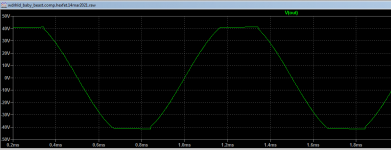
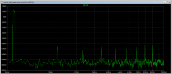
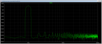
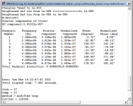
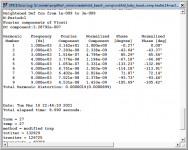
Here is final(?) version of the amp that I'm happy with.
All the basic performance numbers (Thd, FFT profile, SlewRate) are the same in shown in the post #1.
Clipping is OK - there is little 'sticking' visible, but I guess it's OK.
Phase Margin is 48.9 degrees, and Gain Margin is 9.87dB
Screenshots at 1kHz and 10kHz.
Time to plan for the PCB...
Will also try to improve Aksa's version, if possible..
Attachments
-
wdrhld_baby_beast.comp.hexfet.14mar2021.PROBE.asc19.4 KB · Views: 67
-
 clip1.png15.2 KB · Views: 114
 -
 fft_10.png25.3 KB · Views: 107
 -
 fft_1.png25.9 KB · Views: 102
 -
 thd_10.png26.1 KB · Views: 187
 -
 thd_1.png26.3 KB · Views: 196
 -
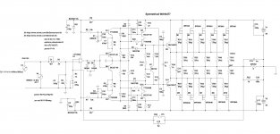 wdrhld_baby_beast.comp.hexfet.14mar2021.jpg296.8 KB · Views: 197
 -
 olg.png57.3 KB · Views: 124
Last edited:
That is a wacky looking Bode plot. People argue about whether it is OK to approach (but not reach!) 180 degree phase before the 0 dB loop gain crossover is reached. The consensus is that it is fine, but your feedback scheme really pushes the idea.
You have built this already, right? I think it will work, and the stability will be fine, but it hurts my brain.
You have built this already, right? I think it will work, and the stability will be fine, but it hurts my brain.
No, I built similar ones, but non-symmetrical, without Hawksford cascode (just single cascode). All of them worked like a champ..
Well, not really all; 4 out of 5.
Well, not really all; 4 out of 5.
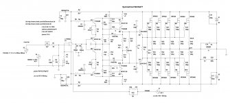
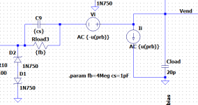
In Damir's testbench you can see the Tian probe between the feedback resistor and the output. It's a voltage source in series and a current source in shunt. You need to add those to your schematic. They don't affect other simulations.
1)Set the voltage source to DC=0, AC={U(-prb)}
Set the current source DC=0, AC={U{prb)}
2) Add these lines to your spice directives:
.param prb=0
.step param prb list -1 1
3) Add this to your plot.defs file in <USERNAME>\Documents\LTspiceXVII:
.func stb() -1/(1-1/(2*(I(VI)@1*V(PROBE)@2-V(PROBE)@1*I(VI)@2)+V(PROBE)@1+I(VI)@2))
4) Make sure all your other AC sources (input source for instance) are set to zero. Only the Tian sources are allowed to have AC.
5) Then, run an AC analysis. In the plot window, right click and choose "Add Traces". In the "Expressions to add:" at the bottom, type stb()
Good luck.
I like to run stability analysis at several points in the signal swing. Here are some details on how I do that.
Tian Stability Plot at multiple points across the Output Swing
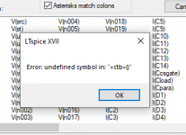
Russell, I wanted to try out your Tian method, but ran into an issue.
I followed your steps, but when I run it, I get:
WARNING: unknown token in: "-1/(1-1/(2*(i(vi)[@]1*v(prb)@2-v(prb)@1*i(vi)@2)+v(prb)@1+i(vi)@2))"
(I changed the 'PROBE' in the function to 'PRB' the first time I got that message but doesn't change things).
Any idea what I'm doing wrong?
Jan
Attachments
Got it - forgot to label the 'probe' node. Back to the drawing board ;-)
Edit: so close - I get the attached error.
Jan
Edit: so close - I get the attached error.
Jan
Attachments
Last edited:
Of course, I can just plot trace:
-1/(1-1/(2*(I(VI)@1*V(PRoBe)@2-V(PRoBe)@1*I(VI)@2)+V(PRoBe)@1+I(VI)@2))
No?
Jan
-1/(1-1/(2*(I(VI)@1*V(PRoBe)@2-V(PRoBe)@1*I(VI)@2)+V(PRoBe)@1+I(VI)@2))
No?
Jan
>That is a wacky looking Bode plot.
>People argue about whether it is OK to approach (but not reach!) 180 degree phase before the 0 dB loop gain crossover is reached.
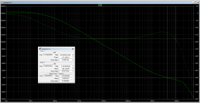
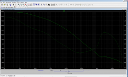
You want to see 'wacky' plot? How about this one (attached).
It's crossing 180 degrees 3 times 😕😕😕
This amp actually worked very well on the test bench, but oscillated like crazy when mounted in the chassis.
That was '1 out 5' failures from the 5 amps I built with this topology..
>People argue about whether it is OK to approach (but not reach!) 180 degree phase before the 0 dB loop gain crossover is reached.
You want to see 'wacky' plot? How about this one (attached).
It's crossing 180 degrees 3 times 😕😕😕
This amp actually worked very well on the test bench, but oscillated like crazy when mounted in the chassis.
That was '1 out 5' failures from the 5 amps I built with this topology..
Attachments
Last edited:
WARNING: unknown token in: "-1/(1-1/(2*(i(vi)[@]1*v(prb)@2-v(prb)@1*i(vi)@2)+v(prb)@1+i(vi)@2))"
Jan
Hi Jan,
I see an extra set of square brackets (marked in red). Also, I think you are conflating the parameter prb with the node name PROBE. In your circuit, that node name is Vend.
Yours: "-1/(1-1/(2*(i(vi)[@]1*v(prb)@2-v(prb)@1*i(vi)@2)+v(prb)@1+i(vi)@2))"
Mine: "-1/(1-1/(2*(I(VI)@1*V(PROBE)@2-V(PROBE)@1*I(VI)@2)+V(PROBE)@1+I(VI)@2)"
I believe your plot.defs function should look like this, for the circuit I see in post #72:
.func stb() -1/(1-1/(2*(I(Vi)@1*V(Vend)@2-V(Vend)@1*I(Vi)@2)+V(Vend)@1+I(Vi)@2))
Naming the node "PROBE" is something that lets me use a plot.defs function, because I always name that node PROBE. It is arbitrary. If your output node is always named Vend, then you can use that instead.
Looking at your Tian probe instantiation, you have the current source Ii upside down. That will give you incorrect results, but not a run-time error. LTspice runs two AC runs. In the first run, Vi is turned on and Ii is off. In the second run Vi is off and Ii is turned on. When I forget to activate the .step line, I get similar errors to what you are getting. Make sure you have the .step directive in your run.
.step param prb list -1 1
And finally, yes, you can just plot the trace
-1/(1-1/(2*(I(VI)@1*V(PRoBe)@2-V(PRoBe)@1*I(VI)@2)+V(PRoBe)@1+I(VI)@2))
provided that the node between the current and voltage sources is named "PRoBe"
Thanks Russell, yes I renamed that node to Probe later.
Not sure it is case sensitive, will check that too.
Funny about those extra square brackets - I thought I copy/pasted it from the post.
I check it out.
Jan
Not sure it is case sensitive, will check that too.
Funny about those extra square brackets - I thought I copy/pasted it from the post.
I check it out.
Jan
I hope it works. I've been where you are, trying to get the Tian probe to work, and getting these weird syntax and run-time errors.
In my IC designs at work, Cadence includes Spectre for spice analysis. It has a .stb function that runs Tian stability analysis without needing a .step directive. It is required in our design methodology at work that we use it for highest accuracy. I felt I should also be using it in my hobby design work.
In my IC designs at work, Cadence includes Spectre for spice analysis. It has a .stb function that runs Tian stability analysis without needing a .step directive. It is required in our design methodology at work that we use it for highest accuracy. I felt I should also be using it in my hobby design work.
Funny - no idea where those brackets come from, they are not in my string; let me check:
.func stb() -1/(1-1/(2*(I(VI)@1*V(Vend)@2-V(Vend)@1*I(VI)@2)+V(Vend)@1+I(VI)@2))
But the error log has:
WARNING: unknown token in: "-1/(1-1/(2*(i(vi)[@]1*v(vend)@2-v(vend)@1*i(vi)@2)+v(vend)@1+i(vi)@2))"
So it appears that LTspice is trying to tell me that the '@' sign is the error, and it stops at the first error.
When I delete the first '@' in the function, the square brackets in the Warning appear at the next instance of the '@'...
.param prb=0
.step param prb list -1 1
BTW what is the syntax, the symbol U in '{U(-prb)}'?
Jan
Last edited:
U is the unit step function. If argument > 0, then U(argument)=1, else U(argument)=0.
prb is -1 on the 1st run and +1 on the 2nd run. On the 1st run, the voltage source is AC 1 and the current source is AC 0. On the 2nd run, the voltage source is AC 0 and the current source is AC 1. The function does math using results from both runs. I'm mystified by the "unknown token" error you are getting.
prb is -1 on the 1st run and +1 on the 2nd run. On the 1st run, the voltage source is AC 1 and the current source is AC 0. On the 2nd run, the voltage source is AC 0 and the current source is AC 1. The function does math using results from both runs. I'm mystified by the "unknown token" error you are getting.
- Home
- Amplifiers
- Solid State
- Symmetrical amp clipping behavior - help needed