Hi Eduard
you are right about the choke, it is from a loudspeaker. i have to read into powersupplys, voltage drop, DCR, chokes, filters etc. to understand what is going on.
What resistor value did you use?
What is the voltage drop across the resistor?
![IMG_20210314_215616[466].jpg](/community/data/attachments/852/852249-56d862b46c429807dd6a19615c72e33d.jpg?hash=VthitGxCmA)
Hello Bubu,
You should check the DC voltage ACROSS the two resistors in parallel which gives a value of 1,485 ohm so voltage drop should be around 1,5 volts.
Like i said before in a private message it looks like the input voltage of the regulator is to high.
I would wait for Doede to react and switch off the unit before you will fry it.
Greetings, eduard
it is 2.2/3.3 ohm ups my wrong. i will try to measure across the two resistors an wait for more adwise.
thanks Bubu
thanks Bubu
Hello,
So then drop across the two resistors combined should be around 1,32 volts.
AND you should try to check DC voltage on the capacitor that is on the input side of the resistor.
I think it will be higher than it should according to the DDDAC blog.
If it is to high you can use a choke with a higher dcr to make the actual input into the circuit lower like i explained in a pm.
greetings, Eduard
it is 2.2/3.3 ohm ups my wrong. i will try to measure across the two resistors an wait for more advise.
thanks Bubu
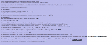
These fragmented measurements and photos are not giving a complete picture.
If you want to know what your power supply is actually doing you need to test all the key metric:
assuming you are looking for 12-13 Volt DC at the output (I recommend for the DDDAC to trim the PSU to 12.5 V by the way to have some headroom
Measurements to be made under the required LOAD (!)
AC measurement:
1) between outside connectors (preferably ~ 30Volt AC)
everything else cause more heat dissipation
2) between middle and outside inputs (this is a check) 2x measurement should read: ~15 Volt
DC Measurement:
Both LEDs are lighting up green? (just check - must be yes of course)
1) Output voltage from PSU
2) between GND and PLUS of first capacitor after the rectifier (preferably ~ 20 Volt DC) - everything else cause more heat dissipation
There is a maximum, depending on the capacitor used (in the standard kit this is 25 Volt DC (!) I see you have your own stuff, so not sure
You can measure this at the 0,1E resistor input (=closest to heatsink rectifier)
3) between GND and output of the Choke
4) between GND and left side of the fuse (when looking at from the side where the fuse is at the edge of the board)
5) between input and output of (so across...) the choke
6) between input and output of (so across...) the parallel power resistors (which are in front of the choke I believe, looking at your picture)
7) between ground and the point directly after the 330 Ohm resistor (see picture) this should not be > 25 Volt DC unless you changed the capacitor behind that point
8) Switch the power supply OFF and let it drain to ~ 0 Volt - now measure Resistance of the parallel R in front of the choke and the choke itself
let us know all these values and we will have a clear and complete picture what is going on 😎
.
Last edited:
I have CCS instead of resistors, how to adjust the DC offset when I have one CCS per DAC chip, it affects both the plus and minus outputs? The current situation is: left channel plus 2.75V and minus 2.70V, right channel plus 2.72V and minus 2.70V.
I was not referring to the CCS, but to the load resistors. Reduce the values of the "plus" load resistors to get the 2.75 V / 2.72 V down to the 2.70 V of the "minus" values. Just use some parallel resistors in the 100-1k Ohm range to get there, or use a trimmer pot. I would actually recommend to tweak the DC imbalance to the low millivolt level.
I didn’t think it was that important for the transformers at the exit. Let's say a 5mV DC offset will give 0.25mA DC current on the Iskra transformer, which has a primary 20 ohms, on other transformers where the resistance is higher, there is even less DC current. Anyway thanks for the advice @mbrennwa.
Hello Bubu,
Copy and paste from Doedes answer:
1) between outside connectors (preferably ~ 30Volt AC)
everything else cause more heat dissipation
2) between middle and outside inputs (this is a check) 2x measurement should read: ~15 Volt
If i read some of your post your voltage is much higher so you will easily end up with close to 24/25 volts on the first cap after the rectifier instead of the desired 20 volts DC.
IF the first cap is rated for 25 volts than better get a 40 volts one i would say.
If you have voltage enough a good reason to use a Lundahl LL2733
Greetings, Eduard
P.s i have a cheaper vintage bourdereau 100 mH 1,3 A 1,3 ohm but i think the ll2733 will be better because of more mH
I measured and hope it is at the right points i measured. At the points that i was not sure, i made measurements at both sides of the resistor.
6) should i change the order of the resistor/choke to choke/resistor?
The only thing that i have changed is the 22000uf 25v Vishay the rest of the blue board are the original components.
6) should i change the order of the resistor/choke to choke/resistor?
The only thing that i have changed is the 22000uf 25v Vishay the rest of the blue board are the original components.
Attachments
![IMG_20210315_133758[542].jpg](/community/data/attachments/854/854434-f7cceeb2a8012a53d9ac64646ca4b388.jpg?hash=98zusqgBKl)
Hello,
I guess Bubu's power supply stopped working because of overheating?
Always a good idea to create a similar load with a BIG power resistor instead of connection a few hundred Euros on parts if you are not sure what you are doing. I always do.
greetings, eduard
I guess Bubu's power supply stopped working because of overheating?
Always a good idea to create a similar load with a BIG power resistor instead of connection a few hundred Euros on parts if you are not sure what you are doing. I always do.
greetings, eduard
The supply is working, i got nervous that the tip122 got hot touching it, after i made copper cooling the tip122 is 50 deg. after 8 hours of music. Elvis is more alive now then before the upgrade🙂
Hello,
The upgrade you mean cooling down the transistor or installing the 15 mH plus resistor combination?
Total DCR will be 1,7 ohm.
If 3,4 ohm ( LL2733) will still give you enough headroom I think it does Elvis will enter your room maybe after a glass of wine.
Greetings, eduard
The upgrade you mean cooling down the transistor or installing the 15 mH plus resistor combination?
Total DCR will be 1,7 ohm.
If 3,4 ohm ( LL2733) will still give you enough headroom I think it does Elvis will enter your room maybe after a glass of wine.
Greetings, eduard
Hi Bubu,
ok, I read all values and congrats, all is 100% fine. The reason you get a hot TIP122 is because your input voltage is a little bit a the high side, hence you are dissipating roughly 7-8 watts. No problem for the TIP, but with this heatsink it will heat up like 50 degrees above room temperature. That is than like 70 to 80 degrees and yes, that feels hot. Nothing will break, but it was a good idea to add some extra cooling 🙂
Nice that Elvis is alive again 😛
oh, no need to change the order of resistor and choke...
edit after reading Eduard post: At point 4) you need like min 18,5 Volt DC, so you could loose another 1,3 volt so add another 1,3 Ohm in series with the choke if you want or using a choke with 1,3 Ohm more.
This will reduce the power dissipation with ~ 20% so ~10 degrees less
Last edited:
Thanks for the feedback
one more question i got a tentlabs 5v Dddac version form a friend and wondering if i should install a cap and what size if yes?
one more question i got a tentlabs 5v Dddac version form a friend and wondering if i should install a cap and what size if yes?
![IMG_20210315_153743[545].jpg](/community/data/attachments/854/854766-c3b7b748e39c6f396b463cf6c803b36e.jpg?hash=w7e3SOOcbz)
Thanks for the feedback
one more question i got a tentlabs 5v Dddac version form a friend and wondering if i should install a cap and what size if yes?
no... just plug it on the mainboard LF50 position. Caps are already on the mainboard...
Hello,
The DDDAC is easily upgraded by doing some minor changes in the power supply.
Already in the eighties the French ( l'Audiophile magazine) published a lot about power supplies.
I have done a lot of changes in power supplies and the VA rating might look as a key element but i think it isnt. Of course you should have some extra VA. But the French and now people like Rod Coleman ( heater power supplies) are telling us to use transformer that have a static screen or a split bobbin construction. Nowadays with lots of SMPS all around your house you better filter garbage starting at the transformer.
The French once made a transistor power amplifier with a toriod power transformer used as an output transformer. So when used as a power transformer it will also not stop a lot of AC garbage.
Of course i take it one step further by using a choke input.
But you can start by using a split bobbin.
Greetings, eduard
I have replaced the stock trafo’s in my dddac psu’s. In went with 80va instead of the stock 25va.
When I connected the Lundahl 16944 chokes in series, the stock trafo’s couldn’t deliver enough juice, and the psu’s slowly shut down. So I have to connect the chokes in parallel, and this works ok.
After a while playing music, I was not happy with the sound, I came to think of my old psu with big trafo’s, which sounded great. And now with the bigger trafo’s , it is just another ballgame, size matters....
Hello Norway,
If the transformer can deliver double the current with the right choke input and you will get the right output voltage i am absolutely sure that a transformer being able to supply 4 times the current will sound worse without a choke. I started my Dddac with a 500 va R core . I think my present transformer is 100 VA maybe 150 VA. It is not that important that is why i dont know.
BUT my input choke is 3000 mH.
Greetings,Eduard
- Home
- Source & Line
- Digital Line Level
- A NOS 192/24 DAC with the PCM1794 (and WaveIO USB input)