PCM1794s are already over the limit (5V as per specs afaik) with 8V applied there.. how is it possible to let's say push their voltage even more from the Tent shunts to let's say 8,5-9Volts?uhm, yes.... that was the reason in the first place to make the "new" board with the embedded shunt....
The 8Volt does the most. The 3,3 V is clearly less (till a point you could say, it is not worth the investment - but that is a very personal decision)
.
One question for Doede:
When I add an output transformer, its winding resistance is connected in parallel with the U/I resistors on the motherboard (34ohm in my DAC). As a result, the DC output voltage drops from 2.7-2.8V to a lower value. Is it necessary to correct the value of the resistor on the motherboard to keep 2.7-2.8V DC at the DDDAC output?
Hi Nixie, no it is not like that. This winding resistance is connected between POS and NEG.... there is only a few mVolt offset, so very little DC current.
The bias current is not affected by this, as that flow towards common (GND)
So when you say it drops, do you think it will drop (it will not) or did you measure that ?
Thank you for your respone. Is there any audible difference between tent and salas shunt on 8v?
I did not try the Salas shunt, so cannot comment on that. I used the Tent, as it is good (I always had good results with Tent) and not unimportant, I could agree on a licensed use of his design as embedded shunt on the new boards.
but hey, feel free to try and listening what you like most
PCM1794s are already over the limit (5V as per specs afaik) with 8V applied there.. how is it possible to let's say push their voltage even more from the Tent shunts to let's say 8,5-9Volts?
I describe the limits on my website -
under: Finding the optimum Bias and Output Voltage
link to dddac website - design
have a good read.
curiosity: why would you like to increase the voltage?
.
So when you say it drops, do you think it will drop (it will not) or did you measure that ?[/QUOTE]
I didn't measure, I just had bad thinking, sorry. I understand now. Thanks Doede.
I didn't measure, I just had bad thinking, sorry. I understand now. Thanks Doede.
Last edited:
Hello,
I am already using a choke -input for both 12 volt mainboard and 5 volt wave IO supply. Switching to a bigger choke for the 12 volt surely gave a more spacious natural sound.
When using PSUD to determine the values of the LCRC or LCLC ( moving the old input choke into second position) should i go for minimum ripple amount or gradually rising of the voltage without ant irregularities. What you will see is gradually rising than one or two overshoot bumps before getting stable. That can be filtered with bigger caps but those can cause higher ripple.
Greetings, eduard
should i go for minimum ripple amount or gradually rising of the voltage without ant irregularities. What you will see is gradually rising than one or two overshoot bumps before getting stable. That can be filtered with bigger caps but those can cause higher ripple.
I'd recommend to avoid the bumps at startup, because they indicate that the filter is not stable and will tend to oscillate. Oscillation just means more work for the regulator downstream of the LC(R|L)C filter. You can usually get the filter stable by increasing the C or DCR values (see my earlier posts about this). Larger C and DCR will also reduce ripple, so thats "double good". 😀
Also, be careful with simulations in Duncan PSUD. It's easy to use a "dummy" load resistor in oder to simulate the load for the filter. However, the load resistor will add damping to the whole system simulated by PSUD, so the bumps / oscillation you get from the simulation are much less than they would be in reality, where the load (=the regulator) has a much lower (dynamic) impedance that the load resistor used in PSUD. If possible, try to use a constant current sink (CCS) as a load in the simulations to obtain more realistic simulation results. (I don't remember if PSUD has a CCS feature)
Hello,
CCS can be used instead of a calculated load resistor.
I know about the effect of changing C value and DCR of choke or resistor. Changes made here will it make possible to have a gentle start up which will in general take a bit longer but sometimes this will make the ripple at bit higher.
These bumps being shown at startup will be there too once the cap are '' fully loaded '' because then the choke should keep the current at a pretty constant level so there arent anymore charging pulses. Or will the bumps just be less big.
So better to go for a gentle rise than trying to minimize the ripple?
Greetings, eduard
So better to go for a gentle rise than trying to minimize the ripple?
I don't think you need to do a tradeoff between the two, as these things should be treated separately. See my previous post. In other words, you should avoid oscillation and minimize the ripple! If you want you can share your PSUD model so we can take a better look at what you're up to.
Hello,
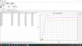
As you can see there are some differences. With higher DCR or bigger caps bumps can be avoided but it seems i will end up with higher ripple.
At the WAVE io i use a 5 volt Belleson regulator that will probably get rid of the last bit of ripple but it could have difficulties filtering those bumps.
Greetings, eduard
Attachments
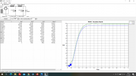
Looking at your simulations, the peak-to-peak ripple is 117 micro Volts. I can't tell the shape of the ripple voltage, but I'd guess it is close to a clean sine (you would need to zoom in to see this), so the RMS ripple voltage will be about 40 micro Volts. That is ridiculously low!
You did not show the ripple from your second simulation, so we cannot compare.
The overshoot in the second simulation shows the tendency for oscillation. I'd avoid this.
You did not show the ripple from your second simulation, so we cannot compare.
The overshoot in the second simulation shows the tendency for oscillation. I'd avoid this.
ok...... putting my moderator cap on 😛 let's not get lost on the ins and outs of Duncan simulations here.... keep it strict to DDDAC use please - discussions like this can take hundreds of posts
thanks !
thanks !
Hello Doede,
Just needed a little bit of guidance .If i would expect it to take more than one page i would have find another way. Now i know where to go. I did have some clue but needed a little extra to find out once again that a good power supply is not just a big transformer and oversized caps. L'Audiophile in France already wrote decades! ago that just throw in a big toroidal transformer isnt the smartest starting point. BUT most people do . There have been some people/ companies who started using EIcore with a static screen or split bobbin to keep garbage on the powerline entering the sensible filaments of their direct heated tubes.
Hope it will keep people investing in the wrong parts. So much easier, better and cheaper to go for a simple CRC ( or CLC my favourite) than just throw in more caps.
A simple rectifier plus one 10000 microfarad cap and a 400 mA load will give 1,6 volt ripple. Changing it to 100000 ripple will remain the same.
Change into CRC 10000 1 ohm 10000 ripple will be 90 millivolt.
Tomorrow i will open up my DDDAC and add some weight.
Greetings, eduard
Thanks Eduard,
After you upgraded your DDDAC PSU, why not draw up a small circuit what you actually have inside as PSU. That would be of value for the thread and a possible inspiration or food for thought for the thread.
of course with a small review on what your impressions were soundwise?
After you upgraded your DDDAC PSU, why not draw up a small circuit what you actually have inside as PSU. That would be of value for the thread and a possible inspiration or food for thought for the thread.
of course with a small review on what your impressions were soundwise?
Happy Easter
A small update from the DDDAC world
It is hard to be consistent in ones blogging I must admit. LOL, I thought I would be constantly blogging after I quit my busy day job one month ago. I spent the March month to pick up on many things which were lying around in my live. Including playing (finally) a lot of golf rounds and work around the house and garden. of course this will go on, but I also feel the thrill for the audio hobby is strong as it never has been before!
read my new blog on what's cooking 😎
happy easter what's cooking/
My Easter eggs
Attachments

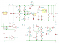
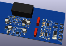
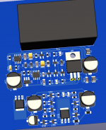
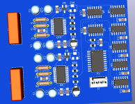
hi! i want to share my work with you. i am a 22yr old student and im in love with designing pcbs. i have good amount of experience in building audio equipment, or should i say i am obsessed with it haha. i am currently designing a dddac with a heavily modified power supply. i removed a spdif input because i dont need it, and it will be only one stack (remember i am a student so money is a big problem-i will add place for up to 4 stacks). i suppose you heard about Kevin Gilmore, a designer of dynalo amp series and a golden reference low voltage power supply (GRLV). This power supply is used in Headamp GSX-mini and Gilmore Lite MK2 headphone amps and it is considered to be the best linear regulated psu. These are one of the best solid state amps. I made my own diy dynalo with GRLV power supply and it measures extremely good. Under max psu load peak to peak ripple is under 1uV. So i thought i could put this power supply instead dddac original one. it is smaller, more efficient, and extremely well regulated. you can set output voltage to 10V and then connect to shunt to further lower the output impedance. i chose the new salas shunt ultrabib 1.3 which is miles better than older version and usen no NOS parts. it has few more components than tent shunt, but it is more powerfull so you could power one channel with one salas shunt (2x PCM1794A). and or course i will put a 5v and 3.3v shunts for logic and usb to i2s card. for 5v it will probably be salas, and for 3.3v i dont know yet. it is a work in progress. instead of transformer i will use a mean well switching psu, then regulate with GRLV and then shunts. i know some of you will say a switching psu is bad, but when regulated with GRLV there is no problem. Headamp Glimore Lite MK2 is a good example with this kind of psu. switchnig psu is smaller, lighter and external capacitors are way smaller than ones needed with transformer. and on top of that, a dac isnt as power hungry as an amp.
below is the scheme and a 3d kicad design. i repeat that it is a work in progress and some thing will change. pictures are there only to give you the idea of this design.
i mentioned i made a dynalo amp, so there are some pictures: amp dac - Google Drive
Doede i know that you might be angry if i would sell these boards, but i have no interest for that. i am just a young student who loves designing pcbs for himself. i hope you like it and i hope gave you a good idea for upgrade.
Attachments
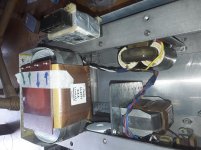
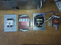
Hello,
I opened up my diy chassis i kind of designed myself with the idea that there could be some some modifications possible without taking apart and having to drill holes in the existing chassis.
As you can see the old 120 VA r core transformer was mounted on a metal plate that had two 90 degrees bends on the up and the down side. In this small bend area there is a line of holes that kind of " connects " with the M6 welded nuts in the bar connecting left and right chassis side. This bar has two lines of these M6 nuts so the parts mounted on this metal plate can be moved closer or further away from the back panel and can also be move sideways because there is row of holes in the bend part that allows ten mm movements in both directions. This plate just being 1 mm thickness and easy to remove it is a piece of cake to remove and all some holes. This plate can be attached to both the bar running in the upper part and the down part of the chassis but even with a 5 kilo choke and a 1 transformer just connection on one bar is enough.
Of course these M6 nuts also serve to mount bottom and top plate.
Greetings,Eduard
Attachments

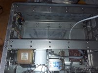
Hello ,
Worthwhile improvement but comes with additional weight . Now 34,9 kilo so happy it isnt at 1,8 meter height anymore but just above the ground.
The typical improvement that comes with a choke improvement this time from a 1000mH to a 6000mH. Some of us now what i am talking about.
Greetings, eduard
Worthwhile improvement but comes with additional weight . Now 34,9 kilo so happy it isnt at 1,8 meter height anymore but just above the ground.
The typical improvement that comes with a choke improvement this time from a 1000mH to a 6000mH. Some of us now what i am talking about.
Greetings, eduard
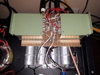
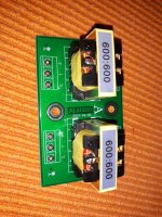
Playing again with green Iskra transformers 600: 600, it seems that I managed to set them to have good bass, without missing highs, or highs to be dominant (both can be achieved). Compensation resistor of 2k on the secondary, combined with approx. 30k input resistance on the preamplifier (a total of 1k88) gives a balanced sound in my system. The output resistance of the DAC is 68 ohms balanced (the less, the better). Now the transformer is slightly undercompensated, the squares have a small peak at the beginning, but when I remove it with a smaller compensating resistance, the high frequencies are a little lacking, they are too soft.
The main advantage over the output capacitors is a better defined and more energetic bass, a better punch and quite a slight softening of the treble which even suits me because of the ribbon on the speakers that sometimes can sound sharp. And it suits me almost twice the voltage from the DAC, for example when I use a buffer with unity gain. I have two more transformers to try, but as far as I can see Iskra will go into this DAC with a probability of 98%. Just to figure out how to fit them inside considering the dimensions, without the left one being next to the main transformer. 50Hz noise is not there at all, they are well armored, but still ...
So if you're playing with 600: 600 transformers, a 5k trimmer on the secondary and turn slowly until it sounds right. Use both, an oscilloscope and ears. I put an ordinary trimmer so that I can see the position of the slider, the one with 25 turns is not practical, since it is parallel to the secondary of 20 ohms. There is nothing to see, and the resistance can be measured only when one end is detached. The trimmer can stay on all the time, allowing you to play while the device is in operation.
Attachments
Last edited:
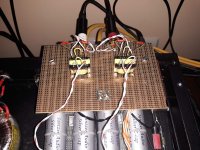
Playing with Chinese transformers 600:600ohms from Aliexpress, $58 pair with postage and a small PCB. Inductance about 6.5H, resistance about 100 ohms (+ -5), slightly smaller on one winding, slightly higher on the other. They have 4 separate 150ohm windings, just like the Iskra. With 2k7 secondary compensation resistors, they sound very good. The problem is that they have a little less bass than with capacitors and Iskra-s. The bass is also more dynamic than with the capacitors, and the treble can be adjusted to be just right.
If I had some minimonitors, nothing would bother me. Compared to Iskra, these are toys. They are wound on permalloy extended E sheets, LC OFC wire (so it says). The sheets are shiny, bright and very thin. I have no idea about the wire quality. They also have a static shield between the windings. If it weren't for a small lack of bass, they would be in the game too.
If I had some minimonitors, nothing would bother me. Compared to Iskra, these are toys. They are wound on permalloy extended E sheets, LC OFC wire (so it says). The sheets are shiny, bright and very thin. I have no idea about the wire quality. They also have a static shield between the windings. If it weren't for a small lack of bass, they would be in the game too.
Attachments
Last edited:
- Home
- Source & Line
- Digital Line Level
- A NOS 192/24 DAC with the PCM1794 (and WaveIO USB input)