Tried to look back and google but could not find the answer, even though I seem to recall this had been discussed before.
What would be the differences in output and thd figures via a 120 vs 133ohm output i/v resistor for a one decker dddac?
I would consider lower output ok, but would not like to sacrifice quality, thanks
What would be the differences in output and thd figures via a 120 vs 133ohm output i/v resistor for a one decker dddac?
I would consider lower output ok, but would not like to sacrifice quality, thanks
should i install 15mH 0.36ohm trafo and a 0.5ohm resistor in series? or leave the original 0.1ohm in?
The blue capacitor is 22000uf the rest of the blue board are the original parts.
I need 12v 1.5A it is to drive a 4 board and a LDOV 3.3v to a Fifopi clean side.
You could use your 0.5 Ohm resistor in series with the 0.36 Ohm inductor, for a total DCR of 0.86 Ohm. The PSU for my 8-deck DDDAC has a total DCR or 0.9 Ohm, and there is still enough voltage drop available for the regulator. With your 4-deck DDDAC you'll have about twice as much voltage drop, which would be plenty.
With a total DCR = 0.86 Ohm and C = 22 uF, you'd need an inductor with L < DCR² x C / 4 = 4.1 mH to prevent any potential for ringing in the CLC filter. In theory, your 15 mH inductor is therefore a bit large any may cause some overshoot of the CLC filter (but nothing very bad). You could increase the total DCR by using a larger resistor value for a total DCR of about 1.66 Ohm (0.36 Ohm + 1.3 Ohm), which would make your filter stable with L = 15 mH, while it would still provide enough voltage headroom for the regulator.
mbernnwa many thanks for the help. when you write 15mH is a bit to large, would it be a better choice to use a 10mH---1ohm?.
Hi Eduard why i am asking is to be sure that i wire all up the right way. this is the first time for me.
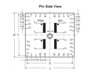
in my logic the transformer should be parallel 18v as you write, but when i measure a 12v DDDAC Blue power supply i measure 34 ohm at the outer holes.
Thanks Bubu
in my logic the transformer should be parallel 18v as you write, but when i measure a 12v DDDAC Blue power supply i measure 34 ohm at the outer holes.
Thanks Bubu
Hello,
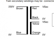
One winding is red plus black
Other winding is yellow plus orange.
Probably if you wanna put them in parallel you connect red plus yellow together. which will go to the rectifier
The other connection will be black plus orange together and that will go to the other ac input of the rectifier.
IF you make the wrong combination of wires it will destroy your transformer.
Take a lot at the Hammond site and it will show how to put secundairies in parallel. Usually they will indicate phase with a dot that is easier.
Greetings, Eduard
Tried to look back and google but could not find the answer, even though I seem to recall this had been discussed before.
What would be the differences in output and thd figures via a 120 vs 133ohm output i/v resistor for a one decker dddac?
I would consider lower output ok, but would not like to sacrifice quality, thanks
For single ended the difference in voltage output would be 120/133 x 1,2 V rms
which = 1,08V ( -0,9dB)
THD will be negligibly smaller, do not worry about this
.
Toroidal transformers are most sensitive to saturation if there is some DC across the primaries. I'd suggest you tweak your DC imbalance to super-duper low levels by adjusting the load resistors accordingly.
I have CCS instead of resistors, how to adjust the DC offset when I have one CCS per DAC chip, it affects both the plus and minus outputs? The current situation is: left channel plus 2.75V and minus 2.70V, right channel plus 2.72V and minus 2.70V. ISKRA transformers have a resonant peak of + 7db, one around 70kHz and the other around 80kHz. The peaks flatten out when I put 1k8 resistors on the secondary. Sounds a little better without compensating resistors. Subjective impressions are better than Cinemag CMLI 600/600 and Jantzen Silver Z capacitors. The sound has more bass, better instrument definition, better 3D images, deeper soundstage, everything sounds more dynamic. The high frequencies sound softer. This suits me because I have ribbon tweeters that can sometimes sound too sharp (even if I compensated for their 7-20kHz rising response), and the bass is only 8.5 inches in a 40l bassreflex box. Since the transformer has two primary windings and two secondary windings, I will try cross-linking to see if a slightly better sound can be extracted. As for the bass, the transformer gives nice squares from 5Hz and up. At 20kHz for the square input, the output is approximately sinusoidal. I'll also try them at the output of the SS preamplifier, I'm just curious how that sounds.
This is great, thanks a lot, Doede!For single ended the difference in voltage output would be 120/133 x 1,2 V rms
which = 1,08V ( -0,9dB)
THD will be negligibly smaller, do not worry about this
.
Going for 120ohm (standard version and sensibly cheaper than custom 133ohm) 0,01% accuracy 0,3W Rhopoint GG102 (planning to drive my balanced pre directly with no caps nor trafos in between as I am already doing with RG Susumus, I am on a one deck dddac) will be a breeze now 🙂 , not meaning to crosspost but linking Paddy's GB thread in case someone else would like to jump on this bandwagon:
https://www.diyaudio.com/forums/gro...gb-resistance-rhopoint-gg102.html#post6566096
Cheers all and stay safe,
Matt.
Hello Bubu,
The FIRST thing you MUST do is is trying to find out how to wire the secundary sides of the transformer correctly.
Greetings, eduard
The FIRST thing you MUST do is is trying to find out how to wire the secundary sides of the transformer correctly.
Greetings, eduard
Hi Eduard
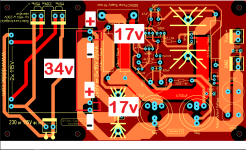
When i look at Doedes print layout i read it as connected in series and not in parallel.
i have attached blue Talema's diagram and pic of layout with voltages i measure.
what i would like to have a conformation on is
should i connect
1. red-orange in the outer holes and black-yellow in the inner holes,
or
2. red-yellow in the outer holes black-orange inner holes?
Thanks Bubu
Attachments
Thanks for the help.
what size of fuse to use with 15mH-1.33ohm in series and transformer setup 1.
Thanks Bubu
what size of fuse to use with 15mH-1.33ohm in series and transformer setup 1.
Thanks Bubu

mbernnwa many thanks for the help. when you write 15mH is a bit to large, would it be a better choice to use a 10mH---1ohm?.
Just use your existing 15 mH choke and 22 mF capacitor with the resistor value I suggested in my earlier post, and you'll have nothing to loose sleep over.
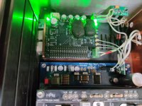
Finally got my power supply installed, and would like to say thanks for the help.
here are some pictures of my setup, this can maybe help other amateurs like me in this operation. i know my layout is a mess but that is how it is, when you can't wait to play with your new toy🙂
After playing music for several hours yesterday and then touching the tip122, it was really hot. i made this quick fix cooling plate, now the tip 122 is 51 degrees Celsius.
i made a cobber shield between the raspberrypi and fifopi some time ago by installing a GPIO Stacking Header – 40 pin, to give me some height for the copper plate and made a hole for the header to go through the plate.
i my opp. to move the fifo away from the pi is a must. By doing this the transient attack was much better.
Attachments


Hello Bubu,
Probably the input voltage to the supply is a bit to high.
Or you need to use another heatsink that can be attached to the circuit. Most of the time adding material to an existing one wont be very effective.
Visit the new blog of Doede. All the info you need is thyere.
Greetings, eduard
Probably the input voltage to the supply is a bit to high.
Or you need to use another heatsink that can be attached to the circuit. Most of the time adding material to an existing one wont be very effective.
Visit the new blog of Doede. All the info you need is thyere.
Greetings, eduard
Hello Bubu,
If your voltage is to high you could also use a lundahl LL2733 choke with more mH and higher DCR. But you would have to check the voltage on the caps to see how much voltage you can drop in the choke.You have the space. The choke you use now is from an old loudspeaker filter i guess.
Greetings, eduard
Hi Eduard
you are right about the choke, it is from a loudspeaker. i have to read into powersupplys, voltage drop, DCR, chokes, filters etc. to understand what is going on. and yes i have read Doedes blog but need some background understanding first. so it is back to school now.
Thanks Bubu
you are right about the choke, it is from a loudspeaker. i have to read into powersupplys, voltage drop, DCR, chokes, filters etc. to understand what is going on. and yes i have read Doedes blog but need some background understanding first. so it is back to school now.
Thanks Bubu
- Home
- Source & Line
- Digital Line Level
- A NOS 192/24 DAC with the PCM1794 (and WaveIO USB input)