Coincidentally I finished this one last night.
I may be slow, but I'm steady.
Dual volume...I’m a fan.
to Nelson Pass #6204
Hello Mr.Pass,
10 units in one night - respect!
That's not
That's ......supersonic......😱
Cheers
Dirk
Hello Mr.Pass,
10 units in one night - respect!
That's not
That's ......supersonic......😱
Cheers
Dirk
Academy Audio Volume Control with IR
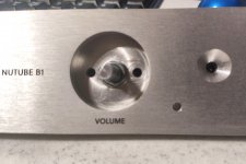
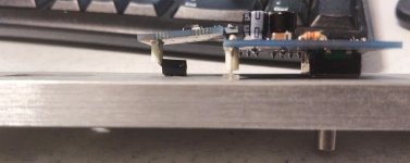
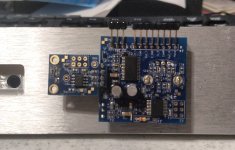
Since others seem to be headed toward using this control in their Korg builds I thought I'd share my mechanical installation of the IR version of the control into my standard Korg chassis.
I had to drill two holes -- one for the LED which shows balance position, and one for the IR sensor.
The LED fit perfectly in a straight hole drilled to fit the diameter of the LED.
For the IR sensor, I drilled a straight hole the diameter of the sensor "bump" and then, because the front panel is 10mm thick, I used a counter-sink drill to open up the hole most of the way to the tip of the sensor. In order for the sensor to fit exactly in the hole I had to first bend the daughter board a little bit to get the sensor closer to the backside of the panel, and then bend the sensor legs a little bit in the other direction to get the sensor to sit flush parallel to the front panel.
Lots of measuring and re-measuring, and it fits perfectly.
Note from the images that the right-angle connector pins will not work in this chassis, they will have to be replaced with straight pins or removed so that wires can be soldered directly to the pads.
Now waiting on some further parts so that I can wire it all together.
Attachments

Hey that is great! Looks awesome so far. I am waiting on my control board and my dc/dc converter. Converter will not be here until around the 24th or so. Thanks for sharing. Love to see when it is done🙂
Since others seem to be headed toward using this control in their Korg builds I thought I'd share my mechanical installation of the IR version of the control into my standard Korg chassis.
I had to drill two holes -- one for the LED which shows balance position, and one for the IR sensor.
The LED fit perfectly in a straight hole drilled to fit the diameter of the LED.
For the IR sensor, I drilled a straight hole the diameter of the sensor "bump" and then, because the front panel is 10mm thick, I used a counter-sink drill to open up the hole most of the way to the tip of the sensor. In order for the sensor to fit exactly in the hole I had to first bend the daughter board a little bit to get the sensor closer to the backside of the panel, and then bend the sensor legs a little bit in the other direction to get the sensor to sit flush parallel to the front panel.
Lots of measuring and re-measuring, and it fits perfectly.
Note from the images that the right-angle connector pins will not work in this chassis, they will have to be replaced with straight pins or removed so that wires can be soldered directly to the pads.
Now waiting on some further parts so that I can wire it all together.
Looks great. Are you going to split the incoming 24v supply into +12/-12v for the muses? Let us know how it sounds...I would really like to have the balance control the muses chips have.
Since others seem to be headed toward using this control in their Korg builds I thought I'd share my mechanical installation of the IR version of the control into my standard Korg chassis.
I had to drill two holes -- one for the LED which shows balance position, and one for the IR sensor.
The LED fit perfectly in a straight hole drilled to fit the diameter of the LED.
For the IR sensor, I drilled a straight hole the diameter of the sensor "bump" and then, because the front panel is 10mm thick, I used a counter-sink drill to open up the hole most of the way to the tip of the sensor. In order for the sensor to fit exactly in the hole I had to first bend the daughter board a little bit to get the sensor closer to the backside of the panel, and then bend the sensor legs a little bit in the other direction to get the sensor to sit flush parallel to the front panel.
Lots of measuring and re-measuring, and it fits perfectly.
Note from the images that the right-angle connector pins will not work in this chassis, they will have to be replaced with straight pins or removed so that wires can be soldered directly to the pads.
Now waiting on some further parts so that I can wire it all together.
Very nice wapo54001. I ordered the same volume control yesterday and digging through my parts box I found a suitable power supply. Looking forward to your impressions of the controls function.
Last edited:
Since others seem to be headed toward using this control in their Korg builds I thought I'd share my mechanical installation of the IR version of the control into my standard Korg chassis.
I had to drill two holes -- one for the LED which shows balance position, and one for the IR sensor.
The LED fit perfectly in a straight hole drilled to fit the diameter of the LED.
For the IR sensor, I drilled a straight hole the diameter of the sensor "bump" and then, because the front panel is 10mm thick, I used a counter-sink drill to open up the hole most of the way to the tip of the sensor. In order for the sensor to fit exactly in the hole I had to first bend the daughter board a little bit to get the sensor closer to the backside of the panel, and then bend the sensor legs a little bit in the other direction to get the sensor to sit flush parallel to the front panel.
Lots of measuring and re-measuring, and it fits perfectly.
Note from the images that the right-angle connector pins will not work in this chassis, they will have to be replaced with straight pins or removed so that wires can be soldered directly to the pads.
Now waiting on some further parts so that I can wire it all together.


Looks great. Are you going to split the incoming 24v supply into +12/-12v for the muses? Let us know how it sounds...I would really like to have the balance control the muses chips have.
I'll use the 24V 500mA supply. The converter itself draws 11mA at idle, the encoder board and the IR board together draw < 15mA (at +/- 12V) so the supply should be able to handle the load without difficulty.
Since I'm not stuffing the LDR setup in there I will use the existing pcb holes for the Korg and try to install the converter (1x1x1/2 inches) on the side wall next to the Korg power resistors.
I'm considering wiring the power switch to be always on (making the switch on the front inoperative). I'd rather consume the power than deal with inadvertent switching and the resulting thump through the system, or is this milder than I imagine it to be?
Connections with ACA you no need reverse outputs of B1K 🙂
Ok, so I did some listening tests where I used a passive switcher (Schiit SYS) to switch the B1K in and out of the signal path to my ACA in real time. I noticed a number of sonic differences (all positive with the B1K in the path) but one of the most striking was some mid-hi instrument notes moving from one speaker predominance to the other. I'm inclined to believe this is due to the phase inversion of the B1K. Has anyone else noticed sound phenomenon with the B1K that they specifically ascribe to phase inversion?
I have no good way to do a switched-phase experiment in real time as I don't have the gear to invert speaker phase without power-off of the ACA. I'd be worried about blowing amp or speakers doing that live.
Is there a ballpark estimate on how long the kits generally take to get back in stock?
6L6 built the last batch, so that is up to him but in general it is non-deterministic and up to the availability of the kit builders. I can tell you now having built 2 kits that it is a serious labor of love and takes a TON of time to get in the professional and easy to use format you have seen delivered by the store kits to-date, so please be patient I am sure they will be replenished eventually... 🙂
--Tom
Is there a ballpark estimate on how long the kits generally take to get back in stock?
I bought everything at diyaudio except the "miscellaneous completion" package which they did not have. I can say that this method is working for me. When I bought, the "miscellaneous" package was the one item that was keeping the kit from being available.
I caused myself headaches because I did not make a complete list of absolutely everything I needed right off the bat, and have now had to order four times from Digikey (partly to support the later addition of an IR volume control from Academy Audio).
Make a list of those miscellaneous parts (note that the 2 100 ohm resistors in the BOM in the PDF should actually be 4), then make a list of all the other parts like 2xDPDT switches, sockets, rubber standoffs etc, and order them from Digikey or Mouser or wherever. Only part I ordered from China was the volume knob and that's probably available locally but I didn't know where to look. Plus, I don't need the knob right away 'cause I plan to use IR for volume.
Last edited:
😀 Most important is your own favoriteI noticed a number of sonic differences

Ok, so I did some listening tests where I used a passive switcher (Schiit SYS) to switch the B1K in and out of the signal path to my ACA in real time. I noticed a number of sonic differences (all positive with the B1K in the path) but one of the most striking was some mid-hi instrument notes moving from one speaker predominance to the other. I'm inclined to believe this is due to the phase inversion of the B1K. Has anyone else noticed sound phenomenon with the B1K that they specifically ascribe to phase inversion?
I have no good way to do a switched-phase experiment in real time as I don't have the gear to invert speaker phase without power-off of the ACA. I'd be worried about blowing amp or speakers doing that live.
Not sure if I have noticed much L/R movement with phase....mostly effects soundstage depth/width/height.
Possible that it is due to a poor tracking volume pot in one of the units. Too me, the Korg increases the perception of space in all directions...possibly at the expense of soundstage precision. So, you may be hearing some of that as well.
- Home
- Amplifiers
- Pass Labs
- B1 with Korg Triode