I've replaced both of BC560C. Q2 Vbe 166mV Q3 Vbe 3.45V
M1 voltage between leg 1-3 is 11.56V (same as output voltage) M2 voltage between leg 1-3 0.585mV. Rload checked 99.6Ohm
Sorry the measured value on M2 is 585mV not 0.585mV
M1 must be wrong type or broken
I've replaced M1, but the voltage between 1-3 is 11.56 after the replacement. Not changed.
The measured M2 voltage is correct or is it too low?
Last edited:
If you don't have a component tester see: #132: How to test MOSFETs with a DMM - a few methods... - YouTube
That's typically alright. Weird. Some joint or something TO-92 must not be working properly. The circuit connections should also check out good with the continuity buzzer.
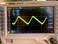
I've put a new M2. I resoldered every joint. (I never had soldering problem) I measured the voltage drop on the R7 and still 0.5-1mV... and the led illuminating very low light. I measured again J1-J3 all between 85 and 100Ohm. I really don't understand. I changed the potmeter, Q2, Q3 M1, M2...
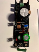
One year ago I made my own version of UltraBiB to one sided pcb, for home production. It worked first time, but a bit noisy. (I think, because of the pcb arrangement) Therefore I bought an official pcb with minikit to be sure everything will be perfect. My DAC don't want the perfect PSU 🙂
Thanks again for the patient and the help for the troubleshooting.
Is there a possibility some 270R is 2K7 or 27K by mistake?
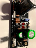
All of 270R and 51R are Dale RN60D from Mouser. I measured the first, when I opened the package, and all are the same. The text are visible 2700F is the 270 Ohm, and 51R0F is the 51 ohm. 470Ohm resistor is PRP
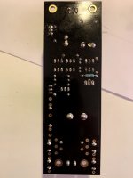
yes, i replaced Vrr. and now it is located under the pcb.Is VRR populated underneath?
Attachments
Last edited:
Onsemi FQP3P20
I replaced it because I measured 11.56V between leg 1-3, but after the replacement I also measured 11.56V between leg 1-3. Is it ok?
The voltage drop on R7 is only a few mV and the Leds illuminating very low light.
I replaced it because I measured 11.56V between leg 1-3, but after the replacement I also measured 11.56V between leg 1-3. Is it ok?
The voltage drop on R7 is only a few mV and the Leds illuminating very low light.
Do you have any other PMOS around to replace, like IRF9610 or similar? Is there normal Vbe on Q1?
*M1 in a working situation should have about 4V Vgs if IRF or 1-2V more if FQP
*M1 in a working situation should have about 4V Vgs if IRF or 1-2V more if FQP
- Home
- Amplifiers
- Power Supplies
- Salas SSLV1.3 UltraBiB shunt regulator