The transformer for the bias is shown as 65V - if we are not sure about the range of required DC voltages, a little increase will not hurt. for best performance, the input voltage should be 20V or so above the desired output range.
Hi rod,
Some questions about the source follower...
-i guess I'll have to apply negative bias to the drain, with enough current (10mA), right? So what are modifications needed, only a transformer with bigger power?
-do you think that driver stage doesn't have enough voltage swing? So what I've figured out is that would be the main function for the source follower (i was thinking of a E186F as well, or the russian equivalent of D3A)
-will the amp remain in pure A class?
Now things are getting difficult, it's the first time I play with source follower and mu follower schemes...
Thank you
I let Rod answer the other questions, just my thoughts on the driver tube choice: D3a (CCS loaded) has enough voltage swing for 20W output power with a normal line level input. The E186F doesn't.
I have tried all the Russian equivalents - I would say that they are unfortunately far from the western tubes' quality.
I have tried all the Russian equivalents - I would say that they are unfortunately far from the western tubes' quality.

Ok, i just can't modify the circuit to suit this source follower thing... Just i don't know this schematic...I let Rod answer the other questions, just my thoughts on the driver tube choice: D3a (CCS loaded) has enough voltage swing for 20W output power with a normal line level input. The E186F doesn't.
I have tried all the Russian equivalents - I would say that they are unfortunately far from the western tubes' quality.
Perhaps I should my Nardi's prephono take care of it, or study a little more 🙂
Thanks for all for the contributions - I apologize my work has kept from my hobbies... or is it the other way around?
I have been corresponding with Ale and have ordred the SiC boards from him, as well as the latest gyrator iteration with presoldred FET and a pair of the source follower boards, though that is a more recent development in this thread.
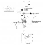
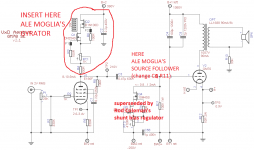
I need to sit and do some calculations, but, in the meantime I am attaching a few of the relevant schematics from Ale's site, he implemented the D3a as the driver in his lastest 300B SE design - as well as a source follower there. IIRC Vincent mentioned that the D3a would be a suitable candidate despite his preference for the E186F SQ - but nonetheless we have two options there and some information.
In other news - I have begun quoting some OPTs and reading a bit into this. With all the funds, I'd go with Monolith and Vincent mentioned, but its appealing to look at more affordable alternatives - namely Fiat (reasonably priced and well regarded), Silk Thailand, as well as Toroidy for a torodial adventure. Lundahl is lets say the gold standard, both in price as performance - not the cheapest but pricing seems feasible.
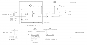
Rod - the voltage double board is produced by whom?
I have been corresponding with Ale and have ordred the SiC boards from him, as well as the latest gyrator iteration with presoldred FET and a pair of the source follower boards, though that is a more recent development in this thread.
I need to sit and do some calculations, but, in the meantime I am attaching a few of the relevant schematics from Ale's site, he implemented the D3a as the driver in his lastest 300B SE design - as well as a source follower there. IIRC Vincent mentioned that the D3a would be a suitable candidate despite his preference for the E186F SQ - but nonetheless we have two options there and some information.
In other news - I have begun quoting some OPTs and reading a bit into this. With all the funds, I'd go with Monolith and Vincent mentioned, but its appealing to look at more affordable alternatives - namely Fiat (reasonably priced and well regarded), Silk Thailand, as well as Toroidy for a torodial adventure. Lundahl is lets say the gold standard, both in price as performance - not the cheapest but pricing seems feasible.
Rod - the voltage double board is produced by whom?
Attachments
cmv260, thank you for your efforts.
easy things first, for power transformers I'll go with italian Raoli's (not the cheapest, but still rugged and never got a disappointment), toroidy has become too $$$$$ for my tastes.
OT, i have to take a look at FIAT (are they italians as well, aren't they?), but the amourfous core is intriguing but costly costly.
Enclosures, hifi2000 is costly but seems to be the way to go.
and now my favourite part:
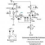
gyrator boards, we need to calculate te load impedance R7 (1/gfs) and the capacitor C1, then understand if the scheme you posted can keep its values (though it states "universal hybrid mu follower).
same applies to source follower values.
Then i would introduce all these changes, including the driver tube with SiC diodes biasing, and sketch a new schematic for "Aeneus v3.0".
To add the raw DC bias supply aforementioned by Rod (really 3 C, 2D, 1R) and his bias boards, one for channel.
I like schematized wrap ups 😀
Should i perhaps leave a line to Ale?
easy things first, for power transformers I'll go with italian Raoli's (not the cheapest, but still rugged and never got a disappointment), toroidy has become too $$$$$ for my tastes.
OT, i have to take a look at FIAT (are they italians as well, aren't they?), but the amourfous core is intriguing but costly costly.
Enclosures, hifi2000 is costly but seems to be the way to go.
and now my favourite part:
gyrator boards, we need to calculate te load impedance R7 (1/gfs) and the capacitor C1, then understand if the scheme you posted can keep its values (though it states "universal hybrid mu follower).
same applies to source follower values.
Then i would introduce all these changes, including the driver tube with SiC diodes biasing, and sketch a new schematic for "Aeneus v3.0".
To add the raw DC bias supply aforementioned by Rod (really 3 C, 2D, 1R) and his bias boards, one for channel.
I like schematized wrap ups 😀
Should i perhaps leave a line to Ale?
Attachments
Last edited:
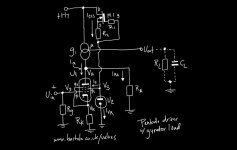
Hello Michelangelo - Here is a schematic of the Power stage, incorporating the mods discussed. This is the version without a source follower; I suspect that the follower would improve it further though.
Ok, dropped a line to Ale Moglia about the source follower implementation. Now the bias power stage (and/or your regulator) need to be adapted... I need to understand what changes does the follower introduce.
> Rod - the voltage double board is produced by whom?
http://lyrima.co.uk/Bias/Bias-RDC-1.pdf
It's a companion kit to the Bias regulator
http://lyrima.co.uk/Bias/Bias-RDC-1.pdf
It's a companion kit to the Bias regulator
Happy to contribute -
Certainly feel free to write Ale - he is definitely an expert though does not do "custom" schematics - so he can show us the door, but we;ll have to do the stepping through. In regards to gyrator in pentode schematic and D3a example, he did clarify that he expresses the CCS as such in the pentode schematic but it is not mentioned in the D3a since the board covers.
Certainly feel free to write Ale - he is definitely an expert though does not do "custom" schematics - so he can show us the door, but we;ll have to do the stepping through. In regards to gyrator in pentode schematic and D3a example, he did clarify that he expresses the CCS as such in the pentode schematic but it is not mentioned in the D3a since the board covers.
Hi rod,
Some questions about the source follower...
-i guess I'll have to apply negative bias to the drain, with enough current (10mA), right? So what are modifications needed, only a transformer with bigger power?
-do you think that driver stage doesn't have enough voltage swing? So what I've figured out is that would be the main function for the source follower (i was thinking of a E186F as well, or the russian equivalent of D3A)
-will the amp remain in pure A class?
Now things are getting difficult, it's the first time I play with source follower and mu follower schemes...
Thank you
The follower adds some more power supply voltages to the design:
The B- input needs a negative supply of a little more than 2x the bias voltage;
the B+ input needs a positive supply of 50-70V
allow about 20mA DC for these. The two negative supplies could be generated by a (example) 240V rms winding with a centre-tap and bridge rectifier.
The bias regulator feeds the follower's IN terminal - the coupling resistor can be around 470-560kΩ.
If you are using the µ-follower then you already get some of the benefit of a low-impedance drive output - so whether the added complexity required is attractive is a matter of judgement. But having a DC-coupled grid has definite advantages.
Ale concurs - though he does state that the advantages of the DC-coupled grid would be most advantageous at higher power/output levels.
If there is no disadvantage i'd say its worth the add'l complexity.
If there is no disadvantage i'd say its worth the add'l complexity.
In terms of Performance, DC-coupled grid is all advantage. The disadvantage is only in the complexity and extra power supplies.
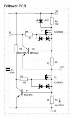
The Follower FETs should be heatsinked, either with little clip-on types, or chassis mounting (use chassis as heatsink). The FETs should be isolated all-plastic TO-220-FP, so no insulator or shoulder washer is needed; TO-220FP packages are resilient to 2500V.
If you have room in the chassis, it would be worth trying, IMHO.
Hi all,
Apologies but haven't read the thread in detail and have been asked to chip in. Unfortunately (like many of us) I'm struggling with free time due to pandemic juggling stuff. Anyhow, hope can help as much as possible.
If you want to understand more how to implement a source follower, please read this: 300B SE Amplifier – Bartola(R) Valves
Of course you can run it without a source follower, however performance and distortion at higher output levels would be better with one. It can be a cathode follower, but is more complicated. The source follower can be as simple as a resistor loaded or CCS loaded as I use. Either way will work well.
You can use Rod's regulators, which are great for this job however you have different options to manage the bias. Where is key to use Rod's regulators is on the DHT filaments, that makes a big big difference, but won't dwell on that as is a well discussed subject.
For the "gyrator" load (aka hybrid mu-follower) you need to set R7 to 470R, R4 to 390K and you're good to operate well at 200-250V levels in the anode. You use P1 to adjust. R6 = 10Meg and C1 = 100nF. You're done that way and will get the best performance of the E186F driver in triode mode.
Benefit is that the output impedance won't be impacted (significantly) by having the 330R cathode resistor unbypassed (as it's a mu-follower) whereas in your diagram is suboptimal as you're taking the output from the anode, not from the mu of the CCS.
The +B of the mu follower should be no greater than 400-450V given the LND150 CCS, unless you want to implement your own board and use higher voltage depletion FET to replace LND150. I wouldn't waste that amount of power in the gyrator IMHO and rather implement a separate HV tap for the driver to provide a sensible 400V. I think you need 350V minimum to provide good headroom for the FETs to operate when swinging 200Vpeak to peak.
Hope this helps?
Cheers
Ale
Last edited:
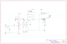
I started to roughly consolidate all of the newer implementations into this rough schematic.
As it looks to complete PSU will need:
1. Existing HV with 800V and 280V Secondaries - feeds output tubes and B2 for Driver (through gyrator)
2. New Bias secondary 65V RMS @ 100mA, and the 80V to feed driver filaments. Rod's HV Doubler does the job here, though come to think of it maybe these get split into two - dual 65V secondaries for the bias, and dual 8V for the filaments. That's 3 donuts so far.
3. Finally, the Raw DC supply, feeding the filament regulators for OP. Rod recommends the Antek Toroid here, 2 to boot. 5 Donuts total.
I need to dig into the values - on all of the components and work through them. Of note, is how G3 is handled in the driver tube. I've run it as pictured - but the other possibility which is actually probably a better play is to anode.
Values for Gyrator - Ale cut us some work there, thankfully, and it seems that C1 and R6 are sensitive components to the ears. Ale mentions using Dale NOS resistors here and I'd imagine quality PIO is welcome for the cap.
I'd appreciate a set of eyes on this, of course, been task switching quite a bit, so surely something I missed.
Attachments
Thank you cmv,
Just a short feedback - with the source follower we've to consider changes in bias ps...
Still don't know what exactly
Just a short feedback - with the source follower we've to consider changes in bias ps...
Still don't know what exactly
I think you have reversed the SiC diodes of the driver. Probably you copied that from my diagram which was wrong. Thanks as didn't realise they were the other way round.
Also would be better to have smaller coupling cap and increased gate bias resistor (R11).
Also you shouldn't ground the -B of the Source Follower. This should be connected to the -B of your raw negative DC (e.g. -250V). See below my diagram as an example:
GM-70 SE Amplifier – Bartola(R) Valves
cheers
Ale
If the one working on the board designs provides mechanical drawings or specifications (Inputs outputs, size and connector type)
I will redesign some existing boards to provide a second source design that is a drop in replacement. For the heaters. Gerbers will be posted online for free, but getting the boards from me gets you technical support.
DHT heater supply design These are not as good as coleman's regs noise wise, however they can survive more abuse due to the 337 built in protection features.
I'm working on a control module for a bias servo up to 300V negative. Its gonna be a complete potted module.
> These are not as good as coleman's regs noise wise, however they can survive more abuse due to the 337 built in protection features.
LM337 will not take more abuse than my carefully selected Power FETs. LM337 is rated for a maximum current of 1.5A. How is it supposed to support the GM-70 filament current of 3.3A? That's an immediate fail.
Making a mechanical copy of my work (and/or Ale's) does not make it a "drop in replacement" - unless the performance is also at the same level. That would require the work of a professional design engineer with decades of experience, in the case of the active circuits, at least. The circuit shown in your pointer certainly does not reach such a level.
My GM-70 filament supplies have used my many constructors here, with high reliability - some for a large part of the 10+ years that they have been available.
A second source for anything is always a good idea even if the replacement may not be up to scratch. A good engineer i knew just ran into the back side of a Semi and the company he works for is as good as done considering the loss of experience.
The circuit i pointed to has quite a bit of noise generated by the 358 and the 337 bandgap reference. That's just something the listener will have to decide if its acceptable.I designed it in such a way that the over temperature protection of the 337 will go into effect far before the 6144 ever gets into trouble. That also means that it will eat any excess dissipation due to high line conditions.
This was never designed to be compete with the Colemans, it was designed to compete with the Tentlabs modules. Because those run a 5.8K/W SK129-50 heatsink made by Fischer and they have failed in the field, which is first hand knowledge from someone who actually builds new production tube up in the Czech republic. He also noted that there are certain reasons having to do with the triple carbonate coating on the filament heaters that rule out a pure current source like your design from the get go. I honestly dont know if this applies equally to thoriated filament tubes.
And to be honest from what ive heard from the field the colemans are the go to choice because the tents run 130 for a pair ex VAT.
Furthermore its not the circuit i had in mind for the GM70 reg either way. Thats an entirely different animal whit a FET that will do four times the dissipation required of it in GM70 regulator duty.
The LT1033 is a drop in replacement for the venerable 337 in most circumstances provided the minimum output capacitance required for stability is met. Furthermore LT guarantees these protection features.
Furthermore, from your assertion that only professional design engineers can produce anything worthwile. You'd allso have to ask ale for his Bsc in electrical engineering(He can't cause he is in ICT I beleive). Otherwise your measuring with two scales.
- Home
- Amplifiers
- Tubes / Valves
- Interesting GM70 scheme... Some questions on the PSU, who helps me please?