No, I don't have any 1" BMS at hand.
What are the differences between them? Do you have all of them measured (under the same conditions)?
No, I don´t have all of them. Some maybe on the same "horn". Conditions wary but if the measurements are done properly the differences are quite small.
When I started with MLSSA back in 1989 I used to save files and moved them from a media to another. When WinMLS came out I did some tests with an old reference and the results were, lets just say, right on. Later WinMLS (Farina sweep) and Clio (my main tool now) do fine if the operator knows how . . .
But back to the topic, could You do some measurements using the PWT response as a reference?
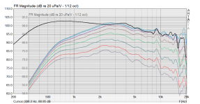
Sure, I did already - on the sand horn and on the PWT. Did you miss that?But back to the topic, could You do some measurements using the PWT response as a reference?
Sure, I did already - on the sand horn and on the PWT. Did you miss that?
Clearly. Or are we talking about different stuff?
Haven´t had the pleasure to test ANY Faital product. Maybe that´s the reason I asked if You could measure some BMS 🙂
I can measure anything but someone would have to provide me with the drivers, which is somewhat complicated.
Arghh... My edit dissapeared....
Yes, I did see the graphs. What I meant was that one could use the PWT graph/data as the reference instead of 0deg or something. PWT represents the power driven in to the WG, no?
Sorry, I cant´t help with the BMS drivers. At the moment I have only a pair of 4538´s.
Yes, I did see the graphs. What I meant was that one could use the PWT graph/data as the reference instead of 0deg or something. PWT represents the power driven in to the WG, no?
Sorry, I cant´t help with the BMS drivers. At the moment I have only a pair of 4538´s.
Great!
One can see the difference. Optimal "loading" vs. WG. I do not know what tools You have but taking the difference (still not the correct term) between let´s say on axis (highest sensitivity) and the PWT would show what the WG does to the "virgin" driver. Sorry, haven´t had to use english for avhile....
One can see the difference. Optimal "loading" vs. WG. I do not know what tools You have but taking the difference (still not the correct term) between let´s say on axis (highest sensitivity) and the PWT would show what the WG does to the "virgin" driver. Sorry, haven´t had to use english for avhile....
I guess it's not that simple. There's also the directivity (which can change independenty of the loading) and different HOMs inside the tube and in the WG. I'm really not sure about meaningfulness of such comparison.
We know the throat impedance of the waveguide from the simulations, don't we.
I don't have that data anymore, only the pictures anyway. But I purchased an ARTA licence in the meantime so I can save the data next time 🙂
We know the throat impedance of the waveguide from the simulations, don't we.
I don't have that data anymore, only the pictures anyway. But I purchased an ARTA licence in the meantime so I can save the data next time 🙂
Last edited:
Ok, I don´t seem to be clear with my thoughts -> language.
Let´s try another way:
In the sims You use some form of input, constant velocity, constant acceleration or something. How about using the power You get from the PWT measurements as a weight to the sims?
Let´s try another way:
In the sims You use some form of input, constant velocity, constant acceleration or something. How about using the power You get from the PWT measurements as a weight to the sims?
You mean to take the normalized simulation data (the polars) and superpose them on the PWT response? No, I don't think that would make any sense.
The only chance to better simulate an actual power radiated from a real driver in a waveguide would be to use (at least) its lumped element model. I don't use that much as it seems to be quite complicated for the CDs, and for the behaviour of the WG directivity and diffraction wise, it has no relevance. But still it's much closer to a real driver than e.g. the constant acceleration assumption, that's for sure.
The only chance to better simulate an actual power radiated from a real driver in a waveguide would be to use (at least) its lumped element model. I don't use that much as it seems to be quite complicated for the CDs, and for the behaviour of the WG directivity and diffraction wise, it has no relevance. But still it's much closer to a real driver than e.g. the constant acceleration assumption, that's for sure.
Maybe not the sims then.
How about taking a PWT measurement, make it the ref and then measure in the far field?
I´m quite sure that I´m not making my self clear here. Not Your fault.
How about taking a PWT measurement, make it the ref and then measure in the far field?
I´m quite sure that I´m not making my self clear here. Not Your fault.
I think he is meaning to to use the measured response as an input to drive the simulation output.You mean to take the normalized simulation data (the polars) and superpose them on the PWT response?
ABEC has the DataDriving= function but it needs a lumped element model and probably a lot of stuffing around for maybe nothing 🙂
"The network-component MeasRadiator is a two pole. After solving the lumped element network there will be a certain potential at its terminals. This potential can be a voltage, force or a sound pressure, depending what the MeasRadiator component represents. If the MeasRadiator represents a typical loudspeaker driver, for example, then the potential is likely to be a voltage.
The MeasRadiator component simply takes its terminal potential and multiplies it with the data from the file which carries the transfer function or sound pressure response. This product eventually drives its associated Pressure_Points or Pressure_Box:
p = Ust·M
with p: sound pressure at the Pressure_Point, Ust potential difference at the terminals of MeasRadiator and M: value from the file."
I was trying to explain what I thought CGL was getting at. I think the point of the function is to be able to use some real world measured data to drive part of the simulation.Why would you do that?
It usually means electrical equivalent circuit. How many fingers are down so far 😉sorry doesn't "lumped element model" translate to = actual, real world response?
I was trying to explain what I thought CGL was getting at. I think the point of the function is to be able to use some real world measured data to drive part of the simulation.
It usually means electrical equivalent circuit. How many fingers are down so far 😉
Fluid: Exactly.
- Home
- Loudspeakers
- Multi-Way
- Acoustic Horn Design – The Easy Way (Ath4)