unfortunately digikey and mouser charge what they can in each respective country. if you want to take advantage of their customs clearance and cheap/free shipping, you just have to deal with it. the USD price converted to AUD is MUCH cheaper; but doesnt tell the whole story.
Kozard,
IME batteries may be low impedance close to DC but not necessarily all across the audio band. Besides people have already tried batteries for AVCC, its no panacea.
IME batteries may be low impedance close to DC but not necessarily all across the audio band. Besides people have already tried batteries for AVCC, its no panacea.
Last edited:
IME batteries may be low impedance close to DC but not necessarily all across the audio band. Besides people have already tried batteries for AVCC, its no panacea.
Wow. Someone actually tried that. Do you recall what type of battery and what the problem/deficiency was?
Mark beat me to it. batteries have of course been tried, but they and their required longish connections are quite inductive, so are not low impedance at all frequencies.
1AWG wire would be 8mm in diameter. i'm pretty sure thats not 1AWG in your pic?
Hmm. I think you are right. Perhaps I can cut a section out of my jumper cables.
not here. its over 8AUD, which is over 5EU. besides. you can get the rest of the parts for 1.25EU? hmmm
Hmmm. Let's see (mouser parts, single items):
1x10uf X7R 1206 187-CL31B106KOHNNWE 0,203 euros
2x4u7uf X7R 1206 791-1206B475K250CT 0,496 euros
1x49k9 0805 thin film 0.5% 754-RR1220P-4992D-M 0,085 euros
Total = 0,78 euros
Sorry for exaggerating, bom is actually below 6 euros 😀
wow, thats a pretty shitty lt3042. bravo 😛
Don't know about that. I have measured it to be quite close to datasheet. And the DUTs I use it in also reach datasheet level so what else to look for?
i'm just joking. I just remember the caps called out in the datasheet (goes into depth in the dev board documentation IIRC) was fairly specific to meet noise performance. by specific, I mean a specific brand and range was called out. I want to say murata. yep, just checked. Gerhard mentioned it made a significant difference vs other brands/ranges when trying to meet their spec. just the 2 caps would be more than 1.2EU.
all good man. different strokes.
I cant speak from experience with this chip as yet. i've researched the hell out of it, done layouts, but not followed through. too many other priorities and parts I already have on hand to use up, so youve got infinitely more first hand experience with it than I do. I will be knocking some up in the coming months to compare. If its as good as its pundits say it is, I may end up using it. I had a layout with the AKM 4499, but then the factory burnt down 🙁. Thus 9038PRO (I need 4 channels)
Last edited:
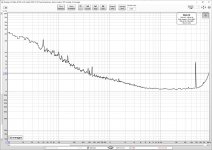
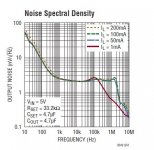
Here is the noise measurement from a 78xx-type LT3042 5V regulator I made just for fun some time ago. It probably uses the same shitty components I listed above. The rising noise above 20kHz is unfortunately due to the soundcard. Anyhow this is definately not the way I would use LT3042. I also included the noise measurement from the datasheet for comparison.
Attachments
added a note on my last comment. Cool, yeah measurement becomes a challenge at these levels. i'm attempting to rectify (or at least alleviate) that with a new ADC, measurement amp and Notch.
Anyway, I wont go any further off topic. My original stance is unchanged; as no doubt is yours 🙂
Anyway, I wont go any further off topic. My original stance is unchanged; as no doubt is yours 🙂
Pulled the dac out of the test box to work on the quality of connections between AK4137 and ES9038Q2M. Trying to get DPLL bandwidth lower requires low connector noise. Will try soldering ribbon cable at AK4137 end, and more connector ground pins at dac I2S input.
Anyway, took the opportunity to take some pics showing the test board and the current state of the dac board including the LT1763 3.3v regulators for clock and VCCA.
What are the two enormous Red WIMA capacitors connected to? (The two that overshadow the top center of your ES9038Q2M board.)
Are those AVCC-R & -L?
Did you solder them in the holes where the stock 100uF 16V ELNA RA3 was?
Does that cap type really make a difference over ELNA RA3 or ELNA Silmic II? Closest I have is a 4.7uF Panasonic CBB. I also have a couple left over 10uF Silmic II.
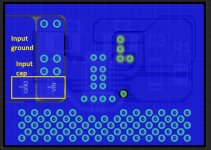
Circuit layout also has a big impact to result, not only the components quality.
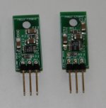
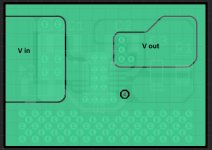
The best circuit a have found so far, you can see it in attached pictures. It is inspired from LT3042 refference design.
The best circuit a have found so far, you can see it in attached pictures. It is inspired from LT3042 refference design.
Attachments

kozard,
The big film caps were something I tried for AVCC. One end of the cap went into the one of the original cap holes, and I drilled a hole though the PCB to ground the other lead on the bottom. No instability problems found using those particular caps. However, I don't know if in the end they are necessarily better or worse than the electrolytics that were also an option. Didn't try to find out for ES9038Q2M.
Since then have made more effort to compare various Vref solutions for AK4499. Some seem to work better than others. Ended up designing a low-noise discrete regulator for it, and choosing caps that worked well with that regulator. The ones I am most happy with so far are film, but they are some custom wound film and foil evaluation prototypes. Jury is still out on whether that's the final solution or not.
Circuit layout also has a big impact to result, not only the components quality.
Would agree that layout is critical for certain circuitry. When I try to give people advice about dac building often seems the part about layout is ignored. People mostly seem to want a schematic, and maybe discuss/debate opinions on what opamps and caps are best. There is so much more to it in reality.
regarding AVCC supply, next thing i will try (next to opamp simple reg i just cobbled, which i'm not super staisfied with with) is dual positive salas regulator, with 3.3v difference between each and then connect the floating output to the load. One reg supply while the other sinks. not sure how it will turn out, but salas regs a in the top 2 regs i have ever used (the other being sigma11 a 5V minimum reg), and i tried quite a few. it's just no convenient heat-wise and performance is limited with lower voltages outputs...
However, if it turns out AVCC is constant current or near that, probably the best reg one could make is a simple salas 3.3v reg. noise-wise, is it unbeatable, to my hear anyway...
However, if it turns out AVCC is constant current or near that, probably the best reg one could make is a simple salas 3.3v reg. noise-wise, is it unbeatable, to my hear anyway...
Last edited:
If one thinks about the resistor element switching in ES9038Q2M, it should be apparent that the best it could do is send current to the I/V opamp and or to send current to ground, say, a mix of the two in some varying proportion such that the current sum is always constant. However, those two current paths may have different enough behaviors and different enough ground return paths to have some effect as seen by the AVCC regulator. May affect how the regulator needs to dynamically respond. When I say, 'may' that means I don't know. Haven't tried to find out, but I suspect there is going to be something to regulate.
What I believe is if it were so simple as that there were really constant current draw then putting a resistor between AVCC and the regulator output should have no audible or measurable effect (except for the added resistor noise, and a constant drop in audio output volume level). That's because the voltage drop across the resistor would be constant, so AVCC voltage would be constant too. Someone want to try it?
What I believe is if it were so simple as that there were really constant current draw then putting a resistor between AVCC and the regulator output should have no audible or measurable effect (except for the added resistor noise, and a constant drop in audio output volume level). That's because the voltage drop across the resistor would be constant, so AVCC voltage would be constant too. Someone want to try it?
Last edited:
Would agree that layout is critical for certain circuitry. When I try to give people advice about dac building often seems the part about layout is ignored. People mostly seem to want a schematic, and maybe discuss/debate opinions on what opamps and caps are best. There is so much more to it in reality.
For your AVCC supplies it looks like you built it on perf board wrapped in places with copper foil? Is that right?
And you removed the 4.7 Ohm series resistor (3.3V to AVCC) that comes on the board, along with the 1206 unknown value ceramic capacitor on the top side right next to the AVCC-R and AVCC-L pins?
I can't see since the film caps are blocking the view of the top of the board there.
- Home
- Source & Line
- Digital Line Level
- ES9038Q2M Board