Okay.
Apls pot wired from left, input, output, ground. (Looking at it from the front.)
I had it wired output, input, ground.
Works beautifully now.
God knows I don't know why.
In 15+ years of building amps from kits and scratch. Amazing.
And the grounds didn't make a difference. (I don't get grounds.)
And the B1 out of phase goes to the ACA out of phase. Voila.
Okay.
Apls pot wired from left, input, output, ground. (Looking at it from the front.)
I had it wired output, input, ground.
Works beautifully now.
God knows I don't know why.
In 15+ years of building amps from kits and scratch. Amazing.
And the grounds didn't make a difference. (I don't get grounds.)
And the B1 out of phase goes to the ACA out of phase. Voila.
Whatever works. Glad you got it up and running. Being able to control the volume is kind of a nice feature to have. Enjoy.
It is better to verify that this connection does not cause a short between input and ground at minimum volume position....I had it wired output, input, ground...
Another Korg B1 completed. Thanks to 6L6 and everyone on the thread. I asked few if any questions, but I ran lots of searches, etc.
I preemptively used rubber stand-offs and some vibration control sheets that I had lying around to head off any microphonics. Mine is not from the pioneer batch anyway, but thought it might be a good idea. The preamp is pretty much silent, running to an ACA and an old pair of Snell JII's. Very nice! Really glad that people like Nelson Pass exist.
I preemptively used rubber stand-offs and some vibration control sheets that I had lying around to head off any microphonics. Mine is not from the pioneer batch anyway, but thought it might be a good idea. The preamp is pretty much silent, running to an ACA and an old pair of Snell JII's. Very nice! Really glad that people like Nelson Pass exist.
As an update, I had an issue with a ticking / clicking sound which was remedied by moving the preamp further from my aleph j power amp. I put my turntable between the amp and the preamp and now no more clicking / ticking. It sounds great, much better than my project pre box dac direct to the amp.
Hello Thomas,
the sub pcb together with the wiring harness - to decouple the NUTUBE from the main pcb - was offered by RScomponents. I've bought one of those kits.
But then I decided to make my own version. I mounted the NUTUBE on an aluminum plate and decoupled it with rubber grommets from the 10mm frontplate. I soldered the wires ( a few cm long) from the NUTUBE directly to the B1 NUTUBE-pcb (my post # 1908 in this thread)
I never had those ringing problems described by many members here!
And I put a little plexiglas-window into the frontplate - you can see your NUTUBE glowing...
Also other members made the NUTUBE visible.
Greets
Dirk 😀
Fantastic. Ill check that out. Thanks!
--Tom
Out of curiosity... For those using a toggle switch as source selector, do you hear a POP when switching between sources?
I went on my B1 Korg for a 3 source "make before brake" selector, but have another project with only 2 sources in mind and no volume pot after to attenuate potential pops, so was wondering what correct part to go for...
Provided there is no pop with toggle switches, I indertand ON-ON could be the right way to go provided they are make before brake? On-OFF-On likely to be a problem in any case?
Many thanks for your help
Claude
An easy build and a sweet sound now driving a pair of ACA v1.6 amps. No hum or microphonics so far. I plan to use the B1K with an M2x amp (as soon as the store gets the boards in stock), but for now it’s replacing a Pass Balanced Zen Line Stage preamp with the ACAs. I’ve been running the ACAs as mono blocks in balanced mode, which I thought sounded better than the single-ended RCA inputs. But with the B1K unbalanced, they sound great as well driving a pair of 95-dB diy speakers. Many thanks to DIYAudio for a great kit.
@ ClaudeG
You can always put 1MegaOhm resistor and cure pop noise from selector sources inputs switch
B1 with Korg Triode 🙂 Best regards
You can always put 1MegaOhm resistor and cure pop noise from selector sources inputs switch
B1 with Korg Triode 🙂 Best regards
Yes indeed Soundhappy, thanks for that.
It was my "worst case" plan, was wondering though if it was really required as I intend to build a complex switchboard with multiple inputs and outputs possibilities.
In short, do toggle switch source selection transmit pops or not?
Thanks
Claude
PS: my make before brake 3-way selector doesn't, as example...
Was wondering because the B1K build guide doesn't seem to mention the 1M resistor with its toggle switch
Thanks!
Thanks!
One of my RCA jacks has a loose positive (signal) post (on the wiring side of the jack). I don’t see a way to tighten it. Is it defective or can I snug it up? It doesn’t look outwardly any different that the rest, but the post wobbles a bit.
It is hard to see from your picture but are you using the washer and both bolts that came with the RCA? These typically come with two thin bolts: one that you snug the RCA and the two plastic washers that isolate it from the chassis, and a washer and another bolt. One you do that, then you slide on the metal washer that contains the negative solder point, and then another bolt over that to shug it all tightly. I can't remember the mm size socket I use but I usually. hold the negative part of the connector on the outside of the chassis with one hand while I carefully tighten the inside of the chassis with a socket until it won't spin any more, while paying attention to keep the positive tip inside the chassis in a concave position (i.e.: so it can hold the solder for the positive connection without it dripping (like if you had it upside down).
6L6 was careful to show this in step 11 of the build guide so please take a another look: B1 with Korg Nutube - diyAudio Guides
But generally the difficulty with this style is that is can become loose over time with vibrations and repeated use, and this is why I use D-style RCAs which have a more solid connection to the chassis and also allow you to torque them down solidly with a socket into the holder part. The bonus is that it is the same sized port so you can easily swap these out for balanced connectors shall you choose to down the road.
--tom
One of my RCA jacks has a loose positive (signal) post (on the wiring side of the jack). I don’t see a way to tighten it. Is it defective or can I snug it up? It doesn’t look outwardly any different that the rest, but the post wobbles a bit.
Sorry one thing I just thought of after I hit reply was that a while back I DID have an RCA with a loose center post but that was because I lingered on it far too long and actually melted the plastic around it so it moved around. Take a careful look at it and see if that is what you might have done too.
--Tom
+1
I am not a SMPS fan, but had to admit that Papa got it 100% right.
To my ears, the SMPS + CRCRC filter wasn't bettered by a big (50x its size) quality regulated lab supply I use only on my bench. I prefered Papa's rec, it scored everywhere better except perhaps in the bass. And I tried hard to convince myself it couldn't be 🙂
I use now an even lower ripple SMPS of the same make, Mark's excellent SMPS filter and 2200uF caps instead of the 1000uF. All this brought very little but noticeable improvements. Diminishing returns though, more a play to hear how far it would go. I reached a point where I don't think any other PS would really make an audible difference on that set up - I call it a day.
Bottom line: go for Papa's recommandation and, if you like to play, enhence it somewhat - job done. In that particular case it really works great without any drawback IMHO.
I hope it helps
Claude
I agree. If people are interested, I'd be happy to support a run of Mark's board as I personally have been looking into getting some myself. There is plenty of room in the B1-K chassis to stick one in right at the DC power inlet point so it would be an easy mod to the existing kit/project.
--Tom
Kind of you, that filter really deserves it and is no brainer. One of these is permanent now in my B1K...
Thanks and well done
Claude
Thanks and well done
Claude
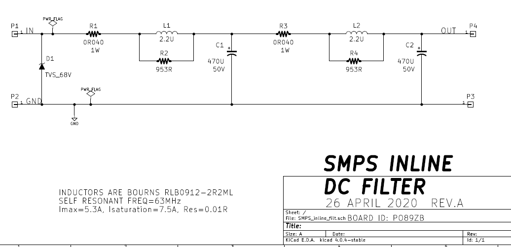
Discussion thread including PCB Gerber file downloads: PO89ZB , an inline DC filter for SMPS wall warts . Preamps, HPA, Korg NuTube, etc
Circuit schematic, click to see it full size and undistorted:
_
Circuit schematic, click to see it full size and undistorted:
_
I'd love two PCBs
I agree. If people are interested, I'd be happy to support a run of Mark's board as I personally have been looking into getting some myself. There is plenty of room in the B1-K chassis to stick one in right at the DC power inlet point so it would be an easy mod to the existing kit/project.
--Tom
In short, do toggle switch source selection transmit pops or not?
Hi Claude - I use a DPDT toggle switch for source and don't get pops.
It does cause the tube to ring unless I operate the toggle gently but thats not too surprising as it's kind of a heavy-duty switch chosen as much for looks as function.
I agree. If people are interested, I'd be happy to support a run of Mark's board as I personally have been looking into getting some myself. There is plenty of room in the B1-K chassis to stick one in right at the DC power inlet point so it would be an easy mod to the existing kit/project.
--Tom
I'd be interested in four boards. Have one I am trying out now.
- Home
- Amplifiers
- Pass Labs
- B1 with Korg Triode