The only R1 is 3 watt's on the B1 schematic but at the inputs 1M are 1/4 watt you can use something bigger if you want 🙂
Source: https://www.firstwatt.com/pdf/art_b1_man.pdf
Source: https://www.firstwatt.com/pdf/art_b1_man.pdf
It's likely something else on that circuit like fluorescent lighting or something interacting w/the SMPS. If I use SMPS devices on the circuit that also powers the condensation pump for my furnace I also get a lot of strange noises.
If I use linear supplies I don't seem to have these problems.
If I use linear supplies I don't seem to have these problems.
Interesting. Are there any off the shelf linear supplies people have had success with? Are people building their own?
Interesting. Are there any off the shelf linear supplies people have had success with? Are people building their own?
I built my own w/a transformer and a lm317 circuit. I am sure there are companies selling prebuilt supplies as well. I have a particular mean well big 10A smps that really doesn't like the condensate pump on my furnace. Big pop when it turns off and on.
You may want to try a different smps supply or even some sort of line filter/power surge protector first. Or, try turning off all the lights or devices on that circuit. You can see what is on the circuit connected to the outlet by shutting off the appropriate breaker at your fuse box.
But also, RFI can travel through the AIR...devices not connected to the circuit can be effected just by being in the area.
Had an interesting episode of ringing that was an apparent single high frequency that grew louder -
- feedback? until I was able to turn off amplifiers. Happened again almost an hour later and was stopped by lifting it off the underlying surface.
- feedback? until I was able to turn off amplifiers. Happened again almost an hour later and was stopped by lifting it off the underlying surface.
Last edited:
I could use a little help, guys. I've tested my PSU and I'm getting 9.02V at T4. I know Nelson Pass says if you're within .5V here you should be OK, but, dang, being this far off leaves me feeling kind of uneasy.
I also don't see what I can do to get closer, given the resistors were all spot-on and the capacitors pretty close to their values.
Would sticking in a different Zener be worth trying or should I just plunge ahead with 9.02V?
Thanks
I also don't see what I can do to get closer, given the resistors were all spot-on and the capacitors pretty close to their values.
Would sticking in a different Zener be worth trying or should I just plunge ahead with 9.02V?
Thanks
There is currently no load so it's going to read a little bit off the stated value. 9-ish volts is fine, carry on. 🙂
Excellent, I'll plunge ahead. Thanks, 6L6, for your help on this and thanks again for the 475s. And for the build guide, of course.

Had an interesting episode of ringing that was an apparent single high frequency that grew louder -
- feedback? until I was able to turn off amplifiers. Happened again almost an hour later and was stopped by lifting it off the underlying surface.
Hi, hade same problem.
I dont know if you have the nutube in a chassie or not.
But I have mine still in a cardbox ( chassie almost done ), just after a litle time I get the (5000Hz) ringing, get louder and louder. Addjust volume dont help.
After I just put my chassie ( missing backplate and top-plate )up side down over my cardbox. No problem, so a good shelded chassi is a must I think.
Frank
Have no problem at all. DC blockers at Nutube out is Black Gate NX High Q 47 uf 6.3. V . Anybody want some PM me. I think I have only used left. But they was very short time in use in an useless DAC. NX is best caps ever made.
Last edited:
Intro .... and Thump Fix
I've not posted to diyAudio before. Not sure if there is some type of introduction protocol? Sorry if I skipped it. Thanks for this site. I'm an audio tinkerer, repairer, system builder, etc.
I read a bit about this build and was intrigued. On a whim I signed up for notification when parts/kits would be available. Early this week I got a notification and bought a kit. Looking back, I wish I bought just the board, fets, and triode and completed the rest myself - oh well. If this gets regular use I'll buy a different enclosure and build my own power supply.
I read about the micro phonic affects and also the on/off thump, but was unprepared for the magnitude of each. Amazon is delivering an eraser or two today. I built it in a few hours and was excited to hear the results .... after which I shelved the thing very quickly. The thump put my amps into protection. Almost as quickly I decided to give it a fair try. I decided that it was interesting, but I probably couldn't live with the thump. I wanted to be able to turn it on/off as I "normally" do with any pre.
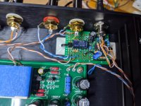
I built a "thump fix" circuit last night and fine tuned it to be acceptable to me. I used parts I had lying around: Small proto board, Lm393 comparator, 12V 2formC relay, 12V zener, a handful of resistors and a few caps. This board is constantly powered from the same 24V supply and uses 20-25mA which seems acceptable based on the wall wart ratings. I use one side of the supplied power switch to interface to my circuit. The led/resistor junction of the original build had to be floated as I used that connection of the switch. At turn on, I had to wait about 16 seconds for the output to stabilize before switching. On turn off, I disconnect the outputs immediately and shunt across the connection with a low value resistor.
If anyone is interested, I can post the schematic.
I've not posted to diyAudio before. Not sure if there is some type of introduction protocol? Sorry if I skipped it. Thanks for this site. I'm an audio tinkerer, repairer, system builder, etc.
I read a bit about this build and was intrigued. On a whim I signed up for notification when parts/kits would be available. Early this week I got a notification and bought a kit. Looking back, I wish I bought just the board, fets, and triode and completed the rest myself - oh well. If this gets regular use I'll buy a different enclosure and build my own power supply.
I read about the micro phonic affects and also the on/off thump, but was unprepared for the magnitude of each. Amazon is delivering an eraser or two today. I built it in a few hours and was excited to hear the results .... after which I shelved the thing very quickly. The thump put my amps into protection. Almost as quickly I decided to give it a fair try. I decided that it was interesting, but I probably couldn't live with the thump. I wanted to be able to turn it on/off as I "normally" do with any pre.
I built a "thump fix" circuit last night and fine tuned it to be acceptable to me. I used parts I had lying around: Small proto board, Lm393 comparator, 12V 2formC relay, 12V zener, a handful of resistors and a few caps. This board is constantly powered from the same 24V supply and uses 20-25mA which seems acceptable based on the wall wart ratings. I use one side of the supplied power switch to interface to my circuit. The led/resistor junction of the original build had to be floated as I used that connection of the switch. At turn on, I had to wait about 16 seconds for the output to stabilize before switching. On turn off, I disconnect the outputs immediately and shunt across the connection with a low value resistor.
If anyone is interested, I can post the schematic.
Cheap and Easy Microphonic Dampening Solution
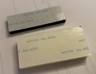
I wanted to follow up on this post. I recently purchased a Nu:Tek Nutube overdrive guitar pedal that is built with the NuTube. Interestingly enough the way they do microphonic isolation is to completely isolate the Nutube from the main circuit board by putting it on its own little board and connected it via a wiring harness. That sub board is then padded both on its underside and on top of the NuTube itself with Nitto No. 500 double-stick foam adhesive pads which you can find here:
https://www.nitto.com/us/en/others/products/file/datasheet/NJ_No.500_No500A_No500AB_EN.pdf
A quick search on Amazon and you find similar products which are essentially weather stripping tape, like the kind you use to seal windows and doors and as you see, this stuff is super inexpensive:
https://www.amazon.com/Adhesive-Wea...foam+self+adhesive+tape&qid=1611003350&sr=8-7
I'd recommend that if there are subsequent runs of the kit, that a couple of pieces of these be included. They are cheap enough and removed all of the microphonic issues I had. The only downside is that it is a shame covering up the cool blue glow from the NuTube.
--Tom
As you saw in the last post, I built my B1K. I've built enough kits and projects like this now that I often skip what appear to be optional recommendations or steps in the build guide. So when I installed the NuTube, I ignored 6L6's build guide recommendations for dampening on the NuTube. Wrong. The first time I connected it to an amplifier and moved the volume pot a half millimeter high-frequency feedback started to come from the speakers. I also could hear an audible hum like a ground loop. Back to the bench...
After looking around at available materials, I first tried using liquid silicone to "glue" a few neoprene washers cut in half, under the NuTube. That had almost no effect on the feedback or hum. Back to the bench.
Next I tried Jim's suggestion of a latex eraser taped above the NuTube. This definitely dampened the high-frequency microphonics but did nothing for the hum. It also would feedback a little when the volume was up past about 9 o'clock. Back to the bench...
The previous week I'd looked at a few guitar pedals that were being made with the NuTube like the Ibanez NuTube Screamer. It turns out NuTube make a kit form of a similar overdrive pedal, so I reviewed the build guide and viola. They tape some thick neoprene onto both sides.
I didn't have any neoprene tape so I looked around at available materials and realized that making a mold on top of the NuTube and filling it with liquid silicone would have the same effect - and if not, I could easily peel it off. It tuns out my creativity was rewarded in that not only did the microphonics disappear at listening levels as loud as I could muster, but the hum disappeared too!
The basic idea of what I did was get some painter's tape and made a box around the NuTube, and then just filled it up. Once it dried, I peeled the tape off and went off listening. It was that simple. The only caveat here is that the sticky side of the painter's tape still stuck a bit to the silicone, so next time I'd either add some kind of oil to the top part of the tape that touches the silicone, or just put another layer of tape over that.
--Tom
I wanted to follow up on this post. I recently purchased a Nu:Tek Nutube overdrive guitar pedal that is built with the NuTube. Interestingly enough the way they do microphonic isolation is to completely isolate the Nutube from the main circuit board by putting it on its own little board and connected it via a wiring harness. That sub board is then padded both on its underside and on top of the NuTube itself with Nitto No. 500 double-stick foam adhesive pads which you can find here:
https://www.nitto.com/us/en/others/products/file/datasheet/NJ_No.500_No500A_No500AB_EN.pdf
A quick search on Amazon and you find similar products which are essentially weather stripping tape, like the kind you use to seal windows and doors and as you see, this stuff is super inexpensive:
https://www.amazon.com/Adhesive-Wea...foam+self+adhesive+tape&qid=1611003350&sr=8-7
I'd recommend that if there are subsequent runs of the kit, that a couple of pieces of these be included. They are cheap enough and removed all of the microphonic issues I had. The only downside is that it is a shame covering up the cool blue glow from the NuTube.
--Tom
Attachments

Welcome to the forum smoovj. I would like to see your schematic if you would like to post it.
I built a power supply for my B1K, and housed it in a separate chassis, as 24 volts is somewhat common for some of the other designs from the store (6-24 crossover as an example). I found a little improvement with the regulated shunt supply, but I didn't bypass any of the RC filtering so I wonder if a more direct connection would have seen greater effect. I didn't make any other changes except for a different volume control which tamed some brightness. In the end, I think the B1K is a lovely sounding piece.
Anyway, welcome to DIYAudio.
Alan
I've not posted to diyAudio before. Not sure if there is some type of introduction protocol? Sorry if I skipped it. Thanks for this site. I'm an audio tinkerer, repairer, system builder, etc.
I read a bit about this build and was intrigued. On a whim I signed up for notification when parts/kits would be available. Early this week I got a notification and bought a kit. Looking back, I wish I bought just the board, fets, and triode and completed the rest myself - oh well. If this gets regular use I'll buy a different enclosure and build my own power supply.
I read about the micro phonic affects and also the on/off thump, but was unprepared for the magnitude of each. Amazon is delivering an eraser or two today. I built it in a few hours and was excited to hear the results .... after which I shelved the thing very quickly. The thump put my amps into protection. Almost as quickly I decided to give it a fair try. I decided that it was interesting, but I probably couldn't live with the thump. I wanted to be able to turn it on/off as I "normally" do with any pre.
I built a "thump fix" circuit last night and fine tuned it to be acceptable to me. I used parts I had lying around: Small proto board, Lm393 comparator, 12V 2formC relay, 12V zener, a handful of resistors and a few caps. This board is constantly powered from the same 24V supply and uses 20-25mA which seems acceptable based on the wall wart ratings. I use one side of the supplied power switch to interface to my circuit. The led/resistor junction of the original build had to be floated as I used that connection of the switch. At turn on, I had to wait about 16 seconds for the output to stabilize before switching. On turn off, I disconnect the outputs immediately and shunt across the connection with a low value resistor.
If anyone is interested, I can post the schematic.
to thomasnadeau #5817
Hello Thomas,
the sub pcb together with the wiring harness - to decouple the NUTUBE from the main pcb - was offered by RScomponents. I've bought one of those kits.
But then I decided to make my own version. I mounted the NUTUBE on an aluminum plate and decoupled it with rubber grommets from the 10mm frontplate. I soldered the wires ( a few cm long) from the NUTUBE directly to the B1 NUTUBE-pcb (my post # 1908 in this thread)
I never had those ringing problems described by many members here!
And I put a little plexiglas-window into the frontplate - you can see your NUTUBE glowing...
Also other members made the NUTUBE visible.
Greets
Dirk 😀
Welcome to the forum smoovj. I would like to see your schematic if you would like to post it.
Alan
Thanks Alan.
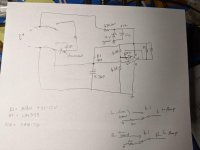
Apologies up-front for the poor hand-drawn schematic and lousy picture.
The switch shown on the left of the schematic is the power switch for the B1K. I had to remove the led/resistor junction as I needed that switch connection.
My circuit is constantly powered but might work OK with switched power?
The relay I had was a 12V unit so I made a 12V supply with a zener and resistor. Maybe could have just put a series resistor with the relay coil and used 24V. The comparator can handle 24V.
With the B1K off, the 4.7uF is shorted, keeping U1pin2 at 0V. The relay will not energize so the amp inputs are shunted to ground thru 120 ohm resistors.
When the B1K is turned on, my 4.7uF charges slowly thru the 4M resistor. At about 16 seconds, the comparator flips, energizing the relay and connecting the B1K outs to the amp inputs.
The 18K resistor provides some hysteresis.
This proto got a bit sloppy. I had used a 1M in series with 560k (not shown) to charge the cap. This gave about 6 seconds of delay. Insufficient. I replaced the 560K with 3 1Mohm to give a total of 4 Mohm. The delay is about 4 seconds /1Mohm.
The LM393 is a dual comparator. I'm going to use the other side to energize a red LED that will indicate when the output is disconnected and waiting for the delay. I also will likely add a "mute" switch that de-energizes the relay.
Eventually the 4.7uF gets charged up to 12V. It gets shorted when the B1K is turned off. It probably does not enjoy this. A smallish series resistor between the switch and the 4.7uF would be better.
The relay I had uses about 4mA. The LM393 can drive this directly.
When the relay energizes, the triode picks that up and I get a little "ting" in the right output .... not bad. I need to work on my microphonics anyway as the eraser fix didn't help me much.
Attachments
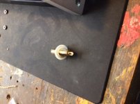
One of my RCA jacks has a loose positive (signal) post (on the wiring side of the jack). I don’t see a way to tighten it. Is it defective or can I snug it up? It doesn’t look outwardly any different that the rest, but the post wobbles a bit.
Attachments
- Home
- Amplifiers
- Pass Labs
- B1 with Korg Triode