I purchase at Farnell.com. They have the 1st class service and variety of good components. They are a bit more expensive but lightning fast. I also buy from Reichelt.de. who are rather good and have good alternative products. Premium, and sometimes rather cheaper but brand products. They also sell "better" stuff at lower price.Where to buy High Quality components in Eu now when I can't use Hificollective anymore?
toutlehautparleur.comWhere to buy High Quality components in Eu now when I can't use Hificollective anymore?
soundimports.eu
lautsprechershop.de
bax-shop.de
tme.eu
mouser.com
reichelt.de
Cannot attach the calc worksheet, where it is possible to change the values, so I'm attaching its pdf conversion made with only one hypothesis. Should anybody be curious, I can send the calc worksheet.
The red zone represents the non-linear zone, when the diode starts conducting up to its full conduction. When the signal crosses the red zone there will be distortion.
The red zone represents the non-linear zone, when the diode starts conducting up to its full conduction. When the signal crosses the red zone there will be distortion.
Attachments
Simply, I have soldered transistors and capacitors and adjusted the bias to the value that corresponds to 20-30 mV at the "Test" points. Note, however, that with low bias there is no sound. Once you increase bias by revolving the potentiometer slowly, counter-clock-wise, the sound will appear. Carefully, this is a wild beast: if you go too fast to high bias, you may burn something. Once done, increase bias slowly, just few mVs per DAY and watch temperature. I wouldn't go higher than 60 °C meassured after many hours under heavy load. You don't have to go too high with bias because this board sounds wonderfully already at 25-30 mV bias.Berlusconi how did you made your Accuphase? I work on it now.
You don't have to do that. That is a good Idea I also have tried but the existing four capacitors are enough to have really good result. Also, the existing fast diodes are quite good. No hum and very little ripple.I have removed the rectifiers on the PCB. I will add more capacitors outside the PCB. Now I wonder what is best supplement. I bought 100 Panasonic's 1200 uf. Want to place them on 2 PCB one for each channel. I also have 4 Kendeil 180.000 uf. Maybe I will place two off them, because in the test of Accuphase the sound is talked about as " meatless" in bass. I will use a 1500 W transformer 36 vac.
The only problem for me was to find good 10.000 uF capacitors with 30mm diameter. I have use Vishay 10.000uF 105C 50V capacitors.
Good luck 🙂
First: don't give-up - this is a good project worth some effort. And I am confident you would be successful, also with implementing the ideas you have just mentioned.We agree that the input stage/VAS with the mods suggested by 3SSS and others works very well in this amp, but the output stage is the weakest point. I have read most of this thread more than once and they have been suggestions for different output stages some including what many say is mandatory, the emitter resistors for the final pair. So it maybe worth to separate the 2 stages in 2 boards
putting the output stage in it's own board to facilitate swapping different output stages.
Just a thought.
And do we do things in our life just because it is easier? I prefer, and I am confident you do too, things that make fun, regardless of effort needed.
I know you can, I can read this between you words. 🙂
My dear Paroxod, this is a mutual agreement.Berlusconi I completely agree with your thoughts.🙂

I prepared a spreadsheet showing when the distortion happens as a consequence of diode switching (the diodes connected to the base of the diamond buffer).
Spreadsheets cannot be attached here, so I attached a pdf showing only one possible situation, while, in the spreadsheet, values can be changed to investigate different situations, speaker impedance will be far different than nominal 8 Ohm.
When the audio signal crosses the red zone, diode transition zone, distortion occurs.
The WHA-217, having the NSCB stage added, requires, at the base of the diamond pairs, a current a little higher than Ispeaker/(hfe(nscb stage)*hfe(diamond pair)), so it doesn't make switch the diodes on the diamond buffer, therefore that type of distortion is absent.
Should anybody be interested, I can send the spreadsheet.
Attachments
Last edited:
WHA-217 simplified version build
Your work and the description in your post #1817 is amazing. Would it be possible to simplify the build of your WHA-217 by using a NHB-108 card which has the servo and three pairs of output transistors all on one board?:
1pcs Luxury Power Amplifier Board AUDIO Imitation DarTZeel NHB 108 Power Amplifier Circuit Board|Amplifier| - AliExpress
"The last stage adopts 3 pairs of ON high-power tubes in parallell." Do you think it could it be turned into a WHA-217 with only a few modifications and jumpers?
(I have asked for a schematic diagram of this card, but I cannot get one)
I have (three) 2x42 VAC toroidal transformers that I would like to use. Also two 6x10.000uF 80V rectifier boards and one Slow Starter Board, similar to yours. What is the minimum amount of output transistors for a WHA-217 variant using 2x42 VAC?
(I hope it is OK that I included one of your photos as a reference?)
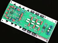
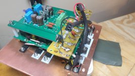
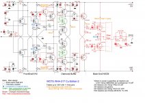
Hello Marigno"Here are some pictures: the original Chinese clone schematic and the WHA-217 CuE (11 pairs are used), drawn in a way that you can easily see differences, and some other pics taken during the work."
Your work and the description in your post #1817 is amazing. Would it be possible to simplify the build of your WHA-217 by using a NHB-108 card which has the servo and three pairs of output transistors all on one board?:
1pcs Luxury Power Amplifier Board AUDIO Imitation DarTZeel NHB 108 Power Amplifier Circuit Board|Amplifier| - AliExpress
"The last stage adopts 3 pairs of ON high-power tubes in parallell." Do you think it could it be turned into a WHA-217 with only a few modifications and jumpers?
(I have asked for a schematic diagram of this card, but I cannot get one)
I have (three) 2x42 VAC toroidal transformers that I would like to use. Also two 6x10.000uF 80V rectifier boards and one Slow Starter Board, similar to yours. What is the minimum amount of output transistors for a WHA-217 variant using 2x42 VAC?
(I hope it is OK that I included one of your photos as a reference?)
Attachments
I am in the same boat, i have 4 of the chinese NHB-108 clones and I would like your help to convert then to WHA-217
@Hattori, drmaftoon
First of all, I have to say that the spreadsheet I uploaded in my last post, is a simplified one, it does not take into account the idle current and some other technicalities. I made a more precise spreadsheet but the result of the two are very similar and the trend is exactly the same.
Second of all, I must say that you need some skill to operate the upgrade to WHA-217, if you do, the mod will be very simple. You need also a variac.
As a first step, you have to remove all the final pairs and their emitter resistors from your board, the final pair you removed could be the new final pairs if you plan to use 3 pairs, which is the minimum number.
On the PCB you must replace one former final pair with another "pilot" pair, which can be the same MJL transistors or something else with 40W and 180Vce at least, and hFE > 80 and a SOA compatible with the job. You cannot get wrong by following my schematic and search the market for pairs with features similar to mine or better.
Mount new emitter resistors 4.7KOhm 5W at least (I used 10W WW ones), connected to the opposite pole of the power line. This should be easy to do on the board itself, the empty collector holes of the removed pairs can be used for the two new resistors.
Then you have to desolder the first and the last TO220 transistor to operate the modification required by the schematic and change the resistors of the CCSs to the new values.
Remove the trimmer and the two resistors with it. Solder the 100KOhm resistor as per schematic.
Remove the 2N5xx1 pairs and replace them with other pairs thermically connected (thermal glue and 0.3mm copper foil you can find on eBay).
As per 3SSS modification, you should use a 2N5551/2N5401 pair in place of the first TO220 pair, I understood this too late. I wouldn't change the two emitter resistors (with one of doubled value) of this pair as I did because it worsens the rejections to power disturbances.
Then you have to think about the arrangement of the remaining components of the NSCB stage; on my PCB it was impossible to make room for the new components and I used another small board, as you saw in my post.
On your PCB you have to cut the track bringing the speaker sensing to the servo, which will be connected to the new speaker point of the added NSCB stage.
You have to find room on the heatsink for the new final pairs you will adopt, plus the pair of temperature sensing transistors, which I connected to the mainboard with a couple of Noctua 3 wires computer fan extensions.
The temperature sensing transistors have only one requirement, the hFE must be > 100, while Vce/Ic are not critical, provided they are > 50V/1A, the case can be any type having the metallic plate that interfaces the heatsink.
As a final pair, you can use the pairs you removed or any good pairs with a matched hFE > 80 and Vce > 180V, whose SOA is compatible with the job; the MT200 final pairs I have are not sold anymore, I recommend not less than 3 pairs, avoiding to buy fakes on eBay.
The output coils are made with 10 turns of AWG14 enameled wire on a 1" plastic pipe, the capacitors close to the coil must be 1000Vdc because they are crossed by a non-negligible current and the 1000V ones are big enough.
The 42Vac transformer will be good, you will get 58+58Vdc voltage, and a little less than 150WRMS, limited in current only by the final pairs and the power supply capabilities, theoretically limited by the CCSs current multiplied by hFE(diamond) X hFE(NSCB). Only theoretically.
What is not good at all are the capacitors on the power supply boards, mine swell all at 70+70V.
Follow the schematic on this post, where I put in place again the original emitter resistors of the first TO220 pair.
As a cabinet, if you don't have any, I would choose a "Dissipante" by HiFi2000 - modushop.biz
If you have any question you can send me a PM, I will answer asap, hoping the power in US will never leave us in blackout!
Attachments
Thank you Marigno for the fast and detailed reply!
I will go ahead and order the bare/unfinished boards from the seller on Ali and then buy good components from a European supplier, so it will be a while before I will actually get to build the amplifier.
I will go ahead and order the bare/unfinished boards from the seller on Ali and then buy good components from a European supplier, so it will be a while before I will actually get to build the amplifier.
Considering that I have transformers that supply 58+58 VDC, how may pairs of output transistors do you recommend for a WHA-217, then? Three are not enough?
With 116Vdc the power obtained should be 135Wrms on 8Ohm.
Three pairs are sufficient in an amplifier with a total feedback loop, here we have no feedback loop from the speaker, so, while the amplifier would work even with 3 only pairs, having a not so low output impedance, I recommend at least 6 pairs to achieve a good DF. If you have more room, you can fill all the space with other pairs. Considering about 10 euro a pair, it is almost a negligible cost compared to the cost of the whole amplifier.
Remember that the two temperature sensing transistors must be close to a final pair, on the same piece of metal, you have to take it into account when designing the mechanical arrangement.
Ok, I see. It was partly a design/look consideration. But if I must use 6 pairs I still would need to mount three pairs separately.
Maybe it is time for a Group Purchase of a circuit board for your WHA-217? 🙂
This company make cards at a very reasonable prices:
PCB Prototype & PCB Fabrication Manufacturer - JLCPCB
How difficult would it be to design the "CAD" file (Gerber?) for a NBH-108 "inspired" card modified into a WHA-217?
Designed for 11 pairs of transistors with the option to cut off the unwanted part? (should you not have a 2x70VDC PSU)
Last edited:
Designing a PCB seems to be very easy.
You need a 2 layers PCB 4oz/ft2 minimum copper thickness, 2.4mm minimum board thickness. This kind of PCB will be very expensive.
You have to replicate the 108's chinese PCB while designing a correct GND path, which does not exist in the 108's PCB, and then design the part related to the NSCB final stage, which is very simple.
I would not integrate the servo in the PCB because my WHA-217 has a stable offset of 1mV. I used the servo because I didn't extend my rehearsal session, but you could deepen yours and decide.
While designing the PCB you have to put the temperature sensing pair far from the main circuit in order to not intercept the heat from the diamond buffer, but only intercept the heat from one final pair. I put the thermal sensing close to the first pair, on the same face of an aluminum angular, thermally decoupled from the main board.
The solution I adopted, point to point wiring for the output pairs, is the best for a high quality sound, being also the cheapest. But, if you want to try to arrange a PCB, sure you can!
I used 11 pairs because I didn't want to crowd too much the assembly, 11 pairs are not mandatory at all, I think 8 would have been the minimum while 16 would have been the maximum.
- Home
- Amplifiers
- Solid State
- Dartzeel amp schematic - build this?