You're welcome Paroxod.🙂Well, everything, struck on the spot, the result is nothing to change, as Dartzel planned, thanks.
Marketing is an art, psychology, based on study of human nature. As Ian Finch so beatifully said "full of sharks".
Sometimes we should stop and try to understand forces that are telling us "Spend... Spending more is better... "
Why are they telling us so? And take into account the effect of the echo chamber. So many, otherwise fine people, are endlessly re-iterating marketing mantra.
Last edited:
I agree that the practical experience of the guys in using different parts is of interest, the theory is also needed, but I don't know much about it, although I've soldered a lot of things over 40 years of practice.
Don't be so modest. In my view, 99% of peope here are pure amatheurs just like two of us. That is all right because this is an amatheur message board, with some exceptional professionals among us. Some other guys pretend to be experts and are giving often missleading advices. Benevolently, I guess.
domenico80 Thank you, but I would like to be more specific about what is suitable for our boards, and where to buy. Brand, model and everything else. And so the name gives me nothing.😕🙂
MUNDORF SUPREME EVO ALUMINIUM OIL
Welcome aboard andrewlebon.Joined the club🙂 pcb just arrived
Do you have components? Could you provide us your BOM?Hello Berlusconi
greetings i dont have the components and the place where i live high
quality components are very hard to get .I am making a list and will
be asking what type of components are best for this amp as i have little
knowledge of electronics i will be needing a little help.
warm regards
Andrew
greetings i dont have the components and the place where i live high
quality components are very hard to get .I am making a list and will
be asking what type of components are best for this amp as i have little
knowledge of electronics i will be needing a little help.
warm regards
Andrew
@andrewlebon
Your determination is indeed commendable. I am sure you will end-up with a fine amplifier, sooner or later. Never give up.🙂
Your determination is indeed commendable. I am sure you will end-up with a fine amplifier, sooner or later. Never give up.🙂
@erlend
Glad to hear from you. 🙂
I have found a diy amplifier which would be in accordance with your frequency response requirements: Accuphase A60+. It is a version with 16 pairs of 2sc5200/2sa1943 per channel 😱. have tested it in a range from 2Hz to 100KHz there is almost no roll-of and it has excellent sound and detail. Bass is remarkable. I have tried it on +-35 and 42. Great amplifier.
🙂Of course.
A60+ refer Golden throat 400W 4R Mirror design Current feedback amplifier board Can match 2SC5200 A1943 / ON/ sanken power tube|Amplifier| - AliExpress
This is a version without main capacitors and transistors. Better, because you can buy reliable devices elsewhere, of course, at higher price. I have purchased from Farnell: ON Semi transistors and capacitors.
It sounds better than I've expected, but be carefull. Use bulb protection during testing and carefully with biasing. I have started with 50 mA and have gradually increased. Be carefull first week and let the board to burn in. Measure the bias at Test point, without any input, otherwise the bias reading will be wrong. You can expect 20W pure class A and up to 200W AB class depending on your transformer.
Good luck.🙂
PS: the board has own power supply on both channels and is impecable: no undesired sounds of any kind whatsoever: just a graveyard silence.
Last edited:
hello Berlusconi, how does it compare to the Dartzeel in sound?@erlend
Glad to hear from you. 🙂
I have found a diy amplifier which would be in accordance with your frequency response requirements: Accuphase A60+. It is a version with 16 pairs of 2sc5200/2sa1943 per channel 😱. have tested it in a range from 2Hz to 100KHz there is almost no roll-of and it has excellent sound and detail. Bass is remarkable. I have tried it on +-35 and 42. Great amplifier.
Better! At least for me: I prefer neutral sound, verbatim reproduction, without unnecessary additions. I wouldn't say that NHB-108 is bad, it is good, but A60+ sounds remarkably good and it is not a clone, it is a Chinese product, a good one, sold as "inspired" by Accuphase A60 and there are no truly original, breakthrough designs elsewhere. All audio products are "inspired" by the "previous art".hello Berlusconi, how does it compare to the Dartzeel in sound?
Initially I wanted to use it as a 2nd fiddle, for the sub woofer but after a week after it burned in and the bias was set, it was a surprise, a positive surprise. Measurements have revealed why.
WOTS WHA-217 Cu Edition - 200W and more from the NHB-108 base.
When I started posting my experience with this amplifier I said that I didn't care about the originality of the circuitry because my goal was to find a job for my Sanken MT200 pairs and two toroidal transformers 50+50Vac 625VA each. So I searched for a board to modify, with no feedback loop from the speaker output. The only one I could find on eBay was the NHB-108.
At that time I didn't know that a thread about my choice was here!
I could accomplish my goal, I have posted my first WHA-217 some time ago and, at that time, I thought I had finished the project.
Then, receiving suggestions from some gents of you (first of all Analog_Sa, being the engine of this last activity of mine) whom I will never end to say thank you, I bought some other PCBs and "good" components, and I started a new adventure in order to improve even more.
I arrived, finally, at the WHA-217 Cu Edition.
Cu Edition stands for the fact that the board, that holds the PCBs and all power transistors, is now made out of copper 3.15mm thick. The previous assembly was made with a 6.3mm aluminum 6063 board, that needed a couple of fans in order to maintain a suitable temperature.
Cu Edition means, overall, a revision to the original circuit as follow:
- a Baxandall super pair is used in the VAS, as per 3SSS's suggestion;
- a 24KOhm resistor connected emitter to emitter replaces the 2 x 12KOhm on the first MJE1503x couple (mod confirmed by 3SSS too);
- all the resistors feeding the zeners are recalculated for 70+70V, in order to maintain the same current as of the original 50+50V project;
- the midpoint trimmer and resistors are removed since they were a source of a noise coming from the power lines, and the voltage micro-fluctuations made the midpoint really unstable; a 100KOhm resistor is placed between the center of the removed trimmer and gnd; the midpoint is now stable, with a small offset, around +/- 1mV without servo and the servo is now keeping the midpoint stably, very close to zero;
- the servo circuitry is not modified, I tried to place a long time constant at its output but it was worse because, when the midpoint reached zero, the time constant was still trying to correct the offset; so I removed any modification and kept it as the original.
What I added to the original NHB-108, since my first WHA-217 edition, is a power stage working in NSCB.
I had to add also a bias/temperature control, now made with a pair 2SC2238/2SA968 (I had a close hfe selection but actually any TO220 NPN/PNP pair having a matched hfe greater than 100 will be good).
I didn't want to buy too fancy components. My choice was made as follows: everything has to be bought from official distributors Mouser or Digikey among available and active components at the moment of purchase, avoiding too expensive items.
Dealing with components on both main and servo boards:
- all film capacitors are polypropylene but the input ones, being ERO MKT1822 (waiting for a job, in a drawer), according to all reviews super-super good for audio; being polypropylene capacitor bigger that the polyester original, in order to fit in the PCB, some capacitances had to be lowered with no problems;
- all electrolytic capacitors are audio grade (Nichicon Muse on main, Elna Silmic II on servo); all original ceramic capacitors are now silver mica ones;
- all small resistors are Vishay MBB/SMA 207 professional 1% 0.6W metal film; all 2W resistors are Vishay PR02 5% metal film, best matched in a bunch of 10 a value;
- bigger resistors had to be wire-wounded 1% ones since no metal film resistors were available for such a power.
I substituted the first MJE1503x pair with 2SC4883A/2SA1859A Sanken and the (original) final pair (now drivers) with 2SC3519/2SA1386 Sanken for the only reason that I had in my drawers a close NPN/PNP hfe selection.
I am so sorry but couldn't follow Domenico's good suggestion to use the NPN/PNP array in place of 2N5551/2N5401, once I looked thoroughly at its datasheet, I learned that the array is really tiny and I'm not equipped to make the eyes to the fleas. I coupled thermically the four transistors all together with thermal glue and a strip of 0.3mm thick copper foil.
Dealing with PCB:
- a correct gnd path does not exist, the gnd is made by the whole upper copper foil; too bad, nothing to do;
- the whole bottom copper foil is insulated; I connected it to the upper foil;
- there are 5 pad holes metalized made in order to connect tracks laying on two sides; since I don't really trust the metallization of the pad-holes for audio purposes, I put a lead inside any of them and soldered them on both sides.
Having in mind that my WHA-217 has to be connected to my Acoustat 1+1 speakers, which generate a lot of disturbance, I had to be very prudential.
It seems that the two Baxandall super pairs are ok but I didn't want to tempt fate too much so, where in doubt, I kept a conservative approach. It is the case of the CCSs: reading around I could not understand if a CCS made out depletion mosfet/resistor would be better than the one made out BJT/zener/resistor so I kept the original CCSs that are not that bad and work without any problem.
I couldn't find any good solution to avoid the zener diodes on the first stage, so they are in place.
And, yes, I'm using the servo that, with good components, is doing very well, far better than any electrolytic capacitor.
What I obtained overperforms my expectations.
This Cu Edition reveals everything in the signal. And the sound is very realistic, I had Karen Carpenter just three meters before me singing with her super clear, articulated and powerful voice, and then Dan Gibson's gregorian chants, Perpetuum Jazzile, and a lot of other music I cannot mention here, where I could immerse myself for a couple of hours. Differences between 1st version and this Cu Edition are not so tiny, a light veil now is removed and the realism is even increased, perhaps the Baxandall super pair does the magic.
Distortion? I really don't know, being a class B push-pull we cannot expect the monotonically decreasing Fourier graphic. I used the Microcap (thanks to Bogdan Borko) to sim my WHA-217 and the distortion is not low at all, trying to improve the distortion I simmed to draw over 20A then decided to come back to my original idea: Class B. We listened at the amplifier almost a whole day to watch television, shows, movies, and so on, with audio coming from the computer: no listening fatigue at all, you really mind turning it off late in the night to sleep.
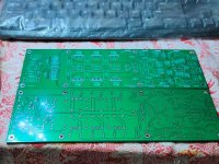
Here are some pictures: the original Chinese clone schematic and the WHA-217 CuE (11 pairs are used), drawn in a way that you can easily see differences, and some other pics taken during the work.
By the way, the two fans are still in place, the temperature is almost the same as the one with the aluminum board. So the super expensive copper boards are not worth it. All the rest YES!!!
When I started posting my experience with this amplifier I said that I didn't care about the originality of the circuitry because my goal was to find a job for my Sanken MT200 pairs and two toroidal transformers 50+50Vac 625VA each. So I searched for a board to modify, with no feedback loop from the speaker output. The only one I could find on eBay was the NHB-108.
At that time I didn't know that a thread about my choice was here!
I could accomplish my goal, I have posted my first WHA-217 some time ago and, at that time, I thought I had finished the project.
Then, receiving suggestions from some gents of you (first of all Analog_Sa, being the engine of this last activity of mine) whom I will never end to say thank you, I bought some other PCBs and "good" components, and I started a new adventure in order to improve even more.
I arrived, finally, at the WHA-217 Cu Edition.
Cu Edition stands for the fact that the board, that holds the PCBs and all power transistors, is now made out of copper 3.15mm thick. The previous assembly was made with a 6.3mm aluminum 6063 board, that needed a couple of fans in order to maintain a suitable temperature.
Cu Edition means, overall, a revision to the original circuit as follow:
- a Baxandall super pair is used in the VAS, as per 3SSS's suggestion;
- a 24KOhm resistor connected emitter to emitter replaces the 2 x 12KOhm on the first MJE1503x couple (mod confirmed by 3SSS too);
- all the resistors feeding the zeners are recalculated for 70+70V, in order to maintain the same current as of the original 50+50V project;
- the midpoint trimmer and resistors are removed since they were a source of a noise coming from the power lines, and the voltage micro-fluctuations made the midpoint really unstable; a 100KOhm resistor is placed between the center of the removed trimmer and gnd; the midpoint is now stable, with a small offset, around +/- 1mV without servo and the servo is now keeping the midpoint stably, very close to zero;
- the servo circuitry is not modified, I tried to place a long time constant at its output but it was worse because, when the midpoint reached zero, the time constant was still trying to correct the offset; so I removed any modification and kept it as the original.
What I added to the original NHB-108, since my first WHA-217 edition, is a power stage working in NSCB.
I had to add also a bias/temperature control, now made with a pair 2SC2238/2SA968 (I had a close hfe selection but actually any TO220 NPN/PNP pair having a matched hfe greater than 100 will be good).
I didn't want to buy too fancy components. My choice was made as follows: everything has to be bought from official distributors Mouser or Digikey among available and active components at the moment of purchase, avoiding too expensive items.
Dealing with components on both main and servo boards:
- all film capacitors are polypropylene but the input ones, being ERO MKT1822 (waiting for a job, in a drawer), according to all reviews super-super good for audio; being polypropylene capacitor bigger that the polyester original, in order to fit in the PCB, some capacitances had to be lowered with no problems;
- all electrolytic capacitors are audio grade (Nichicon Muse on main, Elna Silmic II on servo); all original ceramic capacitors are now silver mica ones;
- all small resistors are Vishay MBB/SMA 207 professional 1% 0.6W metal film; all 2W resistors are Vishay PR02 5% metal film, best matched in a bunch of 10 a value;
- bigger resistors had to be wire-wounded 1% ones since no metal film resistors were available for such a power.
I substituted the first MJE1503x pair with 2SC4883A/2SA1859A Sanken and the (original) final pair (now drivers) with 2SC3519/2SA1386 Sanken for the only reason that I had in my drawers a close NPN/PNP hfe selection.
I am so sorry but couldn't follow Domenico's good suggestion to use the NPN/PNP array in place of 2N5551/2N5401, once I looked thoroughly at its datasheet, I learned that the array is really tiny and I'm not equipped to make the eyes to the fleas. I coupled thermically the four transistors all together with thermal glue and a strip of 0.3mm thick copper foil.
Dealing with PCB:
- a correct gnd path does not exist, the gnd is made by the whole upper copper foil; too bad, nothing to do;
- the whole bottom copper foil is insulated; I connected it to the upper foil;
- there are 5 pad holes metalized made in order to connect tracks laying on two sides; since I don't really trust the metallization of the pad-holes for audio purposes, I put a lead inside any of them and soldered them on both sides.
Having in mind that my WHA-217 has to be connected to my Acoustat 1+1 speakers, which generate a lot of disturbance, I had to be very prudential.
It seems that the two Baxandall super pairs are ok but I didn't want to tempt fate too much so, where in doubt, I kept a conservative approach. It is the case of the CCSs: reading around I could not understand if a CCS made out depletion mosfet/resistor would be better than the one made out BJT/zener/resistor so I kept the original CCSs that are not that bad and work without any problem.
I couldn't find any good solution to avoid the zener diodes on the first stage, so they are in place.
And, yes, I'm using the servo that, with good components, is doing very well, far better than any electrolytic capacitor.
What I obtained overperforms my expectations.
This Cu Edition reveals everything in the signal. And the sound is very realistic, I had Karen Carpenter just three meters before me singing with her super clear, articulated and powerful voice, and then Dan Gibson's gregorian chants, Perpetuum Jazzile, and a lot of other music I cannot mention here, where I could immerse myself for a couple of hours. Differences between 1st version and this Cu Edition are not so tiny, a light veil now is removed and the realism is even increased, perhaps the Baxandall super pair does the magic.
Distortion? I really don't know, being a class B push-pull we cannot expect the monotonically decreasing Fourier graphic. I used the Microcap (thanks to Bogdan Borko) to sim my WHA-217 and the distortion is not low at all, trying to improve the distortion I simmed to draw over 20A then decided to come back to my original idea: Class B. We listened at the amplifier almost a whole day to watch television, shows, movies, and so on, with audio coming from the computer: no listening fatigue at all, you really mind turning it off late in the night to sleep.
Here are some pictures: the original Chinese clone schematic and the WHA-217 CuE (11 pairs are used), drawn in a way that you can easily see differences, and some other pics taken during the work.
By the way, the two fans are still in place, the temperature is almost the same as the one with the aluminum board. So the super expensive copper boards are not worth it. All the rest YES!!!
Attachments
-
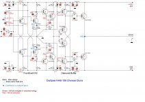 001 Dartzeel NHB-108 Chinese clone schematics.JPG508.5 KB · Views: 682
 -
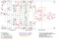 002 WOTS WHA-217.JPG793.2 KB · Views: 696
 -
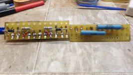
 030 Servo board upgraded.jpg1 MB · Views: 633
 -
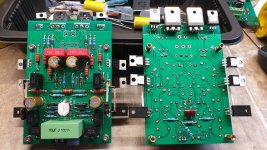 050 Main board upgraded.jpg997.1 KB · Views: 547
 -
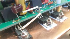 060 Main board upgraded.jpg667 KB · Views: 494
 -
 080 Daughter board.jpg992.6 KB · Views: 274
 -
 090 Assembly.jpg648.5 KB · Views: 278
 -
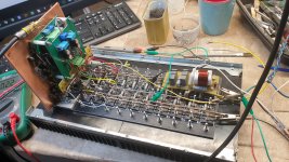 130 One channel ready.jpg1,007 KB · Views: 308
 -
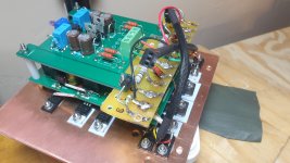
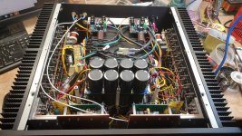 180 Complete assembly.jpg1,013 KB · Views: 310
 -
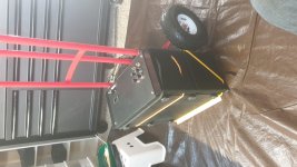 190 Transportation to upstairs.jpg812.8 KB · Views: 337
Wow, marigno, grazie mille!
Thank you for taking the time and effort to write such a long and informative post! I had great time reading all of it. BTW, nice touch with the color-coded schematics 😎
I do not have a 100% clone as well and wanted to try the Baxandall(-ish) super pair tweak for some time now 🙄
PS: Yours is a truly impressive build!
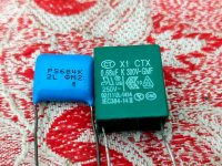
Better no. The green one is supposed to be connected as a filter on AC power lines as an EMI suppression capacitor; about the blue one, I cannot identify it. You must use polypropylene capacitors, they are bigger than polyester ones so, in order to fit them in the PCB, you must reduce their capacitances. Take a look at my last post what was my choice.
About the servo, if you are using it: capacitors MUST be polypropylene 5% tolerance or lower. Take a look at my pics, you must fix some components on the opposite PCB side.
WHA-217 CuE Component list 70+70V
C1 = 470nF (Panasonic ECWFE 450Vdc Polypropylene 5% LS=10mm)
C2 = 10uF (ERO MKT1822 100Vdc MKT LS=27.5mm L=30mm W=13mm)
C3 = 470nF (Panasonic ECWFE 450Vdc Polypropylene 5% LS=10mm)
C4 = 470nF (Panasonic ECWFE 450Vdc Polypropylene 5% LS=10mm)
C5 = 470nF (Panasonic ECWFE 450Vdc Polypropylene 5% LS=10mm)
C6 = 1mF 25V (Nichicon UFW 25V 20% LS=5mm D=10mm H=20mm)
C7 = 1mF 25V (Nichicon UFW 25V 20% LS=5mm D=10mm H=20mm)
C8 = 47pF (Silver mica LS=5mm)
C9 = 150pF (Silver mica LS=5mm)
C10 = 150pF (Silver mica LS=5mm)
C11 = 470nF (Panasonic ECWFE 450Vdc Polypropylene 5% LS=10mm)
C12 = 470nF (Panasonic ECWFE 450Vdc Polypropylene 5% LS=10mm)
C13 = 1uF (Wurth WCAP-FTBP 250Vdc Poplypropylene 5% LS=15mm)
C14 = 1uF (Wurth WCAP-FTBP 250Vdc Poplypropylene 5% LS=15mm)
C15 = 100uF 100V (Nichicon UFW 100V 20% LS=5mm D=10mm H=20mm)
C16 = 100uF 100V (Nichicon UFW 100V 20% LS=5mm D=10mm H=20mm)
Cb1 = 7pF (Silver mica LS=5mm)
Cb2 = 7pF (Silver mica LS=5mm)
Cb3 = 100nF 1KV (Kemet R76 1000Vdc Polypropylene 5% LS=22.5mm)
Cb4 = 100nF 1KV (Kemet R76 1000Vdc Polypropylene 5% LS=22.5mm)
D1 = MUR120RLG (ON Semiconductor)
D2 = MUR120RLG (ON Semiconductor)
Db1 = SBYV28-200 (Vishay)
Db2 = SBYV28-200 (Vishay)
Dz1 = 15V 1W
Dz2 = 15V 1W
Dz3 = 5.1V 1W
Dz4 = 5.1V 1W
Lb1 = 2.3uH (10 turns 14 awg dia 1")
Q1 = 2N5401 (ON Semiconductor)
Q2 = 2N5551 (ON Semiconductor)
Q3 = 2N5551 (ON Semiconductor)
Q4 = 2N5401 (ON Semiconductor)
Q5 = 2SC4883A (Sanken)
Q6 = 2SA1859A (Sanken)
Q7 = MJE15033G (ON Semiconductor)
Q8 = MJE15032G (ON Semiconductor)
Q9 = MJE15033G (ON Semiconductor)
Q10 = MJE15032G (Toshiba)
Q11 = MJE15033G (ON Semiconductor)
Q12 = MJE15032G (ON Semiconductor)
Q13 = 2SC3519 (Sanken)
Q14 = 2SA1386 (Sanken)
Qb1 = 2SC2238 (Toshiba)
Qb2 = 2SA968 (Toshiba)
Qb3 = 2SC3264 (Sanken - multilply for number of pairs)
Qb4 = 2SA1295 (Sanken - multilply for number of pairs)
R1 = 51R (Vishay MBB/SMA 207 professional 1% 0.6W MF)
R2 = 7.5KR 2W (Vishay PR02 5% 2W MF) [70+70V]
R3 = 7.5KR 2W (Vishay PR02 5% 2W MF) [70+70V]
R4 = 56KR (Vishay MBB/SMA 207 professional 1% 0.6W MF)
R5 = 56KR (Vishay MBB/SMA 207 professional 1% 0.6W MF)
R6 = 100KR (Vishay MBB/SMA 207 professional 1% 0.6W MF)
R7 = 100KR (Vishay MBB/SMA 207 professional 1% 0.6W MF)
R8 = 27KR (Vishay MBB/SMA 207 professional 1% 0.6W MF)
R9 = 27KR (Vishay MBB/SMA 207 professional 1% 0.6W MF)
R10 = 3.3KR (Vishay MBB/SMA 207 professional 1% 0.6W MF)
R11 = 360R (Vishay MBB/SMA 207 professional 1% 0.6W MF)
R12 = 360R (Vishay MBB/SMA 207 professional 1% 0.6W MF)
R13 = 3.3KR (Vishay MBB/SMA 207 professional 1% 0.6W MF)
R14 = 36R 2W (Vishay PR02 5% 2W MF)
R15 = 7.5KR (Vishay MBB/SMA 207 professional 1% 0.6W MF)
R16 = 7.5KR (Vishay MBB/SMA 207 professional 1% 0.6W MF)
R17 = 36R 2W (Vishay PR02 5% 2W MF)
R18 = 10KR 2W (Vishay PR02 5% 2W MF) [70+70V]
R19 = 20R (Vishay MBB/SMA 207 professional 1% 0.6W MF)
R20 = 20R (Vishay MBB/SMA 207 professional 1% 0.6W MF)
R21 = 10KR 2W (Vishay PR02 5% 2W MF) [70+70V]
R22 = 100R 2W (Vishay PR02 5% 2W MF) [70+70V to reduce CCS current, not for original schematics]
R23 = 100R 2W (Vishay PR02 5% 2W MF) [70+70V to reduce CCS current, not for original schematics]
R24 = 27R (Vishay MBB/SMA 207 professional 1% 0.6W MF)
R25 = 27R (Vishay MBB/SMA 207 professional 1% 0.6W MF)
Rb1 = 100KR (Vishay MBB/SMA 207 professional 1% 0.6W MF)
Rb2 = 24KR 2W (Vishay PR02 5% 2W MF)
Rb3 = 1.5KR (Vishay MBB/SMA 207 professional 1% 0.6W MF)
Rb4 = 1.5KR (Vishay MBB/SMA 207 professional 1% 0.6W MF)
Rb5 = 1R 2W (Vishay PR02 5% 2W MF)
Rb6 = 4.7KR 10W (Ohmite 40F4K7E 1% 10W WW)
Rb7 = 4.7KR 10W (Ohmite 40F4K7E 1% 10W WW)
Rb8 = 1R 2W (Vishay PR02 5% 2W MF)
Rb9 = 1.2MR (Vishay MBB/SMA 207 professional)
Rb10 = 1.2MR (Vishay MBB/SMA 207 professional)
Rb11 = 0.1R 3W (Generic 3W - multilply for number of pairs)
Rb12 = 0.1R 3W (Generic 3W - multilply for number of pairs)
Rb13 = 10R 5W (Vishay PAC5 5% 5W WW)
Rb14 = 10R 5W (Vishay PAC5 5% 5W WW)
Rb15 = 10R 5W (Vishay PAC5 5% 5W WW)
Servo For WHA-217 CuE Component list 70+70V
C1 = 220nF (Kemet PHE426 Polypropylene 5% LS=5mm)
C2 = 220nF (Kemet PHE426 Polypropylene 5% LS=5mm)
C3 = 220nF (Kemet PHE426 Polypropylene 5% LS=5mm)
C4 = 220nF (Kemet PHE426 Polypropylene 5% LS=5mm)
C5 = 220nF (Kemet PHE426 Polypropylene 5% LS=5mm)
C6 = 220nF (Kemet PHE426 Polypropylene 5% LS=5mm)
C7 = 47uF 35V (Elna Silmic 35V 20% LS=5mm D=12.5mm H=20mm)
C8 = 47uF 35V (Elna Silmic 35V 20% LS=5mm D=12.5mm H=20mm)
C9 = 220nF (Kemet PHE426 Polypropylene 5% LS=5mm)
C10 = 220nF (Kemet PHE426 Polypropylene 5% LS=5mm)
C11 = 47uF 35V (Elna Silmic 35V 20% LS=5mm D=12.5mm H=20mm)
C12 = 47uF 35V (Elna Silmic 35V 20% LS=5mm D=12.5mm H=20mm)
D1 = 1N4149 (ON Semiconductor)
D2 = 1N4149 (ON Semiconductor)
D3 = 1N4149 (ON Semiconductor)
D4 = 1N4149 (ON Semiconductor)
D5 = 1N5934BRLG (On Semiconductor Zener 24V 3W 5%)
D6 = 1N5934BRLG (On Semiconductor Zener 24V 3W 5%)
OP1 = OPA2277
R1 = 1MR (Vishay MBB/SMA 207 professional 1% 0.6W MF)
R2 = 1MR (Vishay MBB/SMA 207 professional 1% 0.6W MF)
R3 = 1MR (Vishay MBB/SMA 207 professional 1% 0.6W MF)
R4 = 1MR (Vishay MBB/SMA 207 professional 1% 0.6W MF)
R5 = 33KR (Vishay MBB/SMA 207 professional 1% 0.6W MF)
R6 = 33KR (Vishay MBB/SMA 207 professional 1% 0.6W MF)
R7 = 1.5KR 2W (Vishay PR02 5% 2W MF) [70+70V]
R8 = 1.5KR 2W (Vishay PR02 5% 2W MF) [70+70V]
R9 = 1.5KR 2W (Vishay PR02 5% 2W MF) [70+70V]
R10 = 1.5KR 2W (Vishay PR02 5% 2W MF) [70+70V]
VR1 = 7815
VR2 = 7915
Last edited:
Wow, marigno, grazie mille!
Thank you for taking the time and effort to write such a long and informative post! I had great time reading all of it. BTW, nice touch with the color-coded schematics 😎
I do not have a 100% clone as well and wanted to try the Baxandall(-ish) super pair tweak for some time now 🙄
PS: Yours is a truly impressive build!
Thank you for your appreciation!
About the Baxandall super pair: you should!!! It is a simple mod.
- Home
- Amplifiers
- Solid State
- Dartzeel amp schematic - build this?