Dave Zan posed some questions on Mabat's waveguide thread about nesting a woofer into the waveguide to reduce centre to centre distance and what effect that would have. I was intrigued to see if I could simulate the effect. It turned out to be much more complicated and time consuming than I thought it would be 🙂
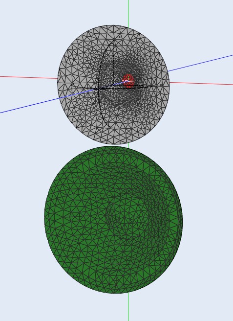
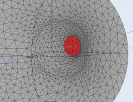
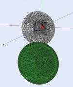
Anyway it forced me to dig deeper into what I was doing with ABEC and 3D CAD to get the profiles and meshes needed to run the simulations. I worked out a method to mesh the waveguide in sections to allow higher resolution near the throat but still allow it to join at a lower resolution further out so it could be combined with the woofer in a single mesh.
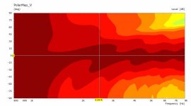
For these simulations I have used an infinite baffle to reduce the element count and to keep an even playing field for diffraction effects. I have also used a smaller waveguide to keep the simulation times down to manageable levels. The woofer is an approximation of a 6" size. The SPL peak is at 3K instead of 1K on the bigger devices. I have limited the frequency range to 800 to 8K.
I have picked a guide with smooth basic response alone so the differences are more obvious. I'll put the versions tested in different posts below.
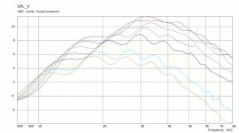
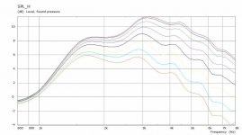
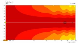
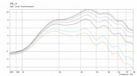
Attached below are the control waveguide SPL and Polar plots.
Anyway it forced me to dig deeper into what I was doing with ABEC and 3D CAD to get the profiles and meshes needed to run the simulations. I worked out a method to mesh the waveguide in sections to allow higher resolution near the throat but still allow it to join at a lower resolution further out so it could be combined with the woofer in a single mesh.
For these simulations I have used an infinite baffle to reduce the element count and to keep an even playing field for diffraction effects. I have also used a smaller waveguide to keep the simulation times down to manageable levels. The woofer is an approximation of a 6" size. The SPL peak is at 3K instead of 1K on the bigger devices. I have limited the frequency range to 800 to 8K.
I have picked a guide with smooth basic response alone so the differences are more obvious. I'll put the versions tested in different posts below.
Attached below are the control waveguide SPL and Polar plots.
Attachments
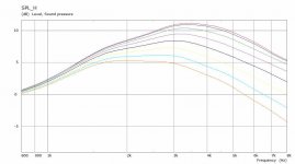
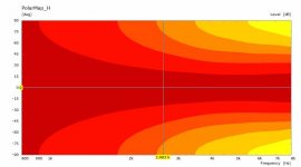
This is the change in response by adding a simulated woofer profile below the waveguide almost as close as possible. It introduces about a 0.5 to 1dB ripple in the horizontal as well as a more even vertical as would be expected. Not so pretty vertically anymore. The boundaries are rigid in the simulation and in reality they may be less pronounced.
Attachments
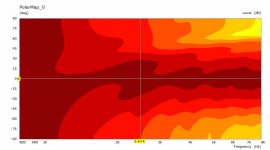


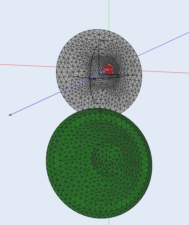
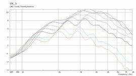
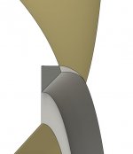
This is the response by moving the woofer up 20mm so it cuts into the bottom of the waveguide. I cut the rebate with the waveguide then the waveguide with the rebate and removed the residue. It could be smoothed better for for these purposes the geometry will be meshed anyway.
Result is more ripple and worse vertical the lower in frequency you go. This seems to me that the degradation in polar would make crossing higher more necessary with this arrangement. To make a true comparison a driven woofer and crossover would need to be simulated to see the end result.
I am now more happy that I bought the HF1440 to allow me to cross lower and get the woofer further away from the waveguide.
I am now interested in simulating a freestanding guide with a woofer box below to see if the improved termination allows the pattern to be disturbed less by the woofer.
Attachments
-
 Waveguide+Woofer Split IB V SPL.jpg50.7 KB · Views: 176
 -
 Waveguide+Woofer Split IB H Polar.jpg26.7 KB · Views: 164
 -
 Waveguide+Woofer Split IB H SPL.jpg49.5 KB · Views: 201
 -
 Split Detail.jpg24.2 KB · Views: 190
 -
 Waveguide Split Zoom.jpg229.9 KB · Views: 179
 -
 Waveguide Woofer Split.jpg109.5 KB · Views: 1,141
 -
 Waveguide+Woofer Split IB V Polar.jpg28.4 KB · Views: 165
Great comparison but a bit hard to evaluate. The bass is not in the simulation so one can't asess (total summed FR of LF & HF) the eventual positive in the lesser c-c of the last variant - I suppose this is why one would like them closer.
If it would be possible to do a difference plot between the 2 it would be easier to understand the differences... but maybe that is not so easy. Sorry for just wanting things and not contributing - if I only had the skills....
//
If it would be possible to do a difference plot between the 2 it would be easier to understand the differences... but maybe that is not so easy. Sorry for just wanting things and not contributing - if I only had the skills....
//
Given that your CD plays down to 500 Hz or so, its feasible to horizontal slot load the woofer below it for the penultimate reduction in CTC (ultimate being Synergy). I built a TD15Hslot loaded woofer that I equalizes flat and smooth to 600 Hz with just this in mind but never got around to the waveguide. It was actually a high aspect ratio conical horn rather than a pure slot.
The c2c spacing is not going to get signifiantly smaller unless a multiple entry horn. At optimal crossover frequency c2c would be still about one wavelenght if the baffle mounted woofer and waveguide have similar size. Few centimeter on a 30cm c2c distance isn't very meaningful and if it is causing the ripple I'd say not worth the effort.
A Multiple entry horn would get the drivers to 1/4wl c2c which would be meaningful. However the ripple could be worse, simulation could show what it is. Mabat has mentioned few times in the ath thread that the mouth termination has more effect on quality than the throat. This could mean the ripple could be a bit less when the woofer (tap) is near throat than at the mouth. Simulation of a waveguide with "midrange tap(s)" would be cool to see 🙂
A Multiple entry horn would get the drivers to 1/4wl c2c which would be meaningful. However the ripple could be worse, simulation could show what it is. Mabat has mentioned few times in the ath thread that the mouth termination has more effect on quality than the throat. This could mean the ripple could be a bit less when the woofer (tap) is near throat than at the mouth. Simulation of a waveguide with "midrange tap(s)" would be cool to see 🙂
Last edited:
My slot/horn was only 4" tall. 12" wg with 12" woofer gives 12" ctc. 12" wg with 4" slot gives 8" ctc.
^ that reduction is already in the meaningful territory. Is there problem with resonances in the slot due to it's depth and width?
Last edited:
Wouldn't we need the woofer enclosure too? And ideally look at the woofer/tweeter crossover to see the effects of that.
I know you're concentrating on waveguide effects (the intrusion of the waveguide by the woofer position to be specific), but crossover effects will influence total results.
Indeed a slot or port ala Synergy could be used to get woofer position closer and create somewhat of the band-pass needed as a byproduct.
One could even place two smaller slot loaded woofers (side by side) closer to the waveguide like bwaslo did on the small syns.
Last edited:
Exactly where my mind is. DIYSG has these 16 ohm woofers and I already grabbed four of them for this purpose.One could even place two smaller slot loaded woofers (side by side) closer to the waveguide like bwaslo did on the small syns.
Specs:
The following is an a average of the two samples, V(as) was measured using added mass method (31 grams)
R(e) 9.35
F(s) 66Hz
Q(ts) .45
Q(es) .48
Q(ms) 8
L(e) 1.65mH
M(ms) 18.25g
V(as) 22.5l
SPL (@2.83V) 92.5
Last edited:
Thanks for the thoughts and comments
In this example the change is from 170mm to about 150mm CTC for a crossover in the 2 to 3K range so I think it is more that you thought but perhaps still not worth the trade.
cookiemonster77 made some synergy ABEC sims a long time ago, the taps were lumped element simulated rather than BEM meshed so more like Hornresp in that sense. A comparison of the impact on the polar from having taps in the horn vs having a woofer below would be interesting. I actually want to build a two way speaker with woofer and waveguide to hear it for myself first. If the CNC seems up to it after that who knows maybe I'll try an optimised waveguide synergy.
Suitable midrange cone, for bandpass mid in Unity horn.
I am sceptical of trying to model the lower crossover of the waveguide based on an ideal membrane. With a CD lumped element model as seen in Mabat's thread the lower rolloff is modified significantly. In reality I think the real driver would need to be measured in the waveguide and enclosure.
The slot loaded woofers like bwaslo used would probably be a better directivity match to the waveguide than a 15 used behind a slot.
No issue with wanting things 🙂 This isn't a walk in the park for me either and the last few posts represents about three full days worth of effort. I will look into a difference plot it shouldn't be hard to make but it might be hard to interpret. What I can do is put them in a gif so you can optically average them. In reality the difference isn't huge and most of the damage is done just by putting the woofer below the waveguide. It might also be instructive to see how far away from the waveguide it needs to be to reduce that damage. The basic difference in lobing due to crossover spacing could be seen more easily in Vituix based on piston size to determine just how much reduction is needed to have a beneficial effect.Great comparison but a bit hard to evaluate. The bass is not in the simulation so one can't asess (total summed FR of LF & HF) the eventual positive in the lesser c-c of the last variant - I suppose this is why one would like them closer.
If it would be possible to do a difference plot between the 2 it would be easier to understand the differences... but maybe that is not so easy. Sorry for just wanting things and not contributing - if I only had the skills....
//
That is a possibility but I would imagine that the directivity from the slot would not match the directivity of the waveguide very well when placed below. The woofer and waveguide match very well at 800Hz and below.Given that your CD plays down to 500 Hz or so, its feasible to horizontal slot load the woofer below it for the penultimate reduction in CTC (ultimate being Synergy). I built a TD15Hslot loaded woofer that I equalizes flat and smooth to 600 Hz with just this in mind but never got around to the waveguide. It was actually a high aspect ratio conical horn rather than a pure slot.
Few centimeter on a 30cm c2c distance isn't very meaningful and if it is causing the ripple I'd say not worth the effort.
A Multiple entry horn would get the drivers to 1/4wl c2c which would be meaningful. However the ripple could be worse, simulation could show what it is. Mabat has mentioned few times in the ath thread that the mouth termination has more effect on quality than the throat. This could mean the ripple could be a bit less when the woofer (tap) is near throat than at the mouth. Simulation of a waveguide with "midrange tap(s)" would be cool to see 🙂
In this example the change is from 170mm to about 150mm CTC for a crossover in the 2 to 3K range so I think it is more that you thought but perhaps still not worth the trade.
cookiemonster77 made some synergy ABEC sims a long time ago, the taps were lumped element simulated rather than BEM meshed so more like Hornresp in that sense. A comparison of the impact on the polar from having taps in the horn vs having a woofer below would be interesting. I actually want to build a two way speaker with woofer and waveguide to hear it for myself first. If the CNC seems up to it after that who knows maybe I'll try an optimised waveguide synergy.
Suitable midrange cone, for bandpass mid in Unity horn.
The enclosure is the infinite baffle to reduce the impact of diffraction to see the effects of the woofer more clearly. I started out with a Free space enclosure but the effects of the enclosure made it even more difficult to see the difference. Now I have a good IB script and mesh I can cut that out of an enclosure which will be next in line.Wouldn't we need the woofer enclosure too? And ideally look at the woofer/tweeter crossover to see the effects of that.
I know you're concentrating on waveguide effects (the intrusion of the waveguide by the woofer position to be specific), but crossover effects will influence total results.
Indeed a slot or port ala Synergy could be used to get woofer position closer and create somewhat of the band-pass needed as a byproduct.
One could even place two smaller slot loaded woofers (side by side) closer to the waveguide like bwaslo did on the small syns.
I am sceptical of trying to model the lower crossover of the waveguide based on an ideal membrane. With a CD lumped element model as seen in Mabat's thread the lower rolloff is modified significantly. In reality I think the real driver would need to be measured in the waveguide and enclosure.
The slot loaded woofers like bwaslo used would probably be a better directivity match to the waveguide than a 15 used behind a slot.
re'
That is a possibility but I would imagine that the directivity from the slot would not match the directivity of the waveguide very well when placed below. The woofer and waveguide match very well at 800Hz and below.
Recall I said the slot was actually a high aspect ratio conical horn. You can make the side walls of the conical horn match the angle and depth of your axially symmetric waveguide and get a good horizontal directivity match. What you won't get is good vertical control unless you go with woofer slots both above and below.
That's why for this application it doesn't make sense with a single woofer which is what I have. The multiple small drivers is interesting but I have been down a similar road already 😉
Do you remember Wayne Parham of pi speakers. His waveguide speakers had a lobe in the main beam that he had to deal with because of CTC. What he did was use time misalignment to aim the null between the sidelobe and the main beam at the floor in such a way as to minimize the floor bounce null.
But that is only at the crossover frequency in a narrow bandwidth, soon above and below that there is energy to the floor and ceiling again so it is kind of automatic and the only thing one can do with the 1WL c2c, a consequence. It is an interesting thing though and might affect positively to listening experience if the crossover frequency is right, but not sure if it has any merit in the end. the crossover frequency is pretty much nailed to the driver and waveguide size which I think has more important compromises on it alread (like the size🙂. All multiway speakers with waveguide have the vertical lobes due to c2c, unless the crossover is way lower than the waveguide has effect on, so it is a trade-off in the system design and should be appreciated as such.
Anyway, thanks fluid for the cool thread. Not many brave hearts that can do ABEC simulations in here!
Anyway, thanks fluid for the cool thread. Not many brave hearts that can do ABEC simulations in here!
Last edited:
Your welcome 🙂 ABEC is an awesome tool, there are limitations but it can answer many questions. I have found that many things I thought would be better are not and that intuition and speakers don't actually go that well together 😉Anyway, thanks fluid for the cool thread. Not many brave hearts that can do ABEC simulations in here!
Hi Fluid,
Great thread, thanks for sharing.
I will be very interested in understanding your objectives for the bass section of this build, if that makes sense?
I am considering a similar build with 15" high efficiency woofer section that can deliver big bass for music without needing subs in a home setting.
Great thread, thanks for sharing.
I will be very interested in understanding your objectives for the bass section of this build, if that makes sense?
I am considering a similar build with 15" high efficiency woofer section that can deliver big bass for music without needing subs in a home setting.
Last edited:
The objectives of the woofer section for my build is to match directivity of the waveguide at the crossover frequency which was originally going to be ~800Hz but with the purchase of the HF1440 could well be down towards 500Hz depending on measurements. I want to try vented and maybe passive cardioid cabinets to hear them for myself.
This masters thesis shows some positive listening tests done a prototype cardioid system
https://aaltodoc.aalto.fi/bitstream/handle/123456789/43595/master_Kantamaa_Olli_2020.pdf?sequence=2&isAllowed=y
I have talked to DonVK about trying to model a cardioid system in ABEC, but it was another thing that became complicated fast 😉
- Home
- Loudspeakers
- Multi-Way
- 2 way waveguide speaker build ABEC modelling