Thanks guys 🙂 You supported the creation of this thread and it's basically done for all of you.
Without try is no joy, .. said people on Titanic 😀 But that is not our story ..
People can build and sell this DAC, handmade as their hobby, or collecting parts and sell it as kits with some profit - basically it is not profit 😀 Nice to see someone doing it with the idea of reducing costs or making work easier for people, just a tedious process
Moreover anyone can take the idea, do improvements, better PCB and sell it under own brand, why not .. there is still 65000 chips on rocelec 😀 (but this will never happen, because the delta-sigma parameters of economical digital sound rolled over the world 🙄).
>>telling half of the story in many posts
Exactly that is how some sales started
DIY forum == every detail has to be shared for "fully diy people" as the main intention. And let the buy opportunity as a good intention for "half diy people".
You are wrong again 😀 ... it is not the original, but rather a part of the train ...
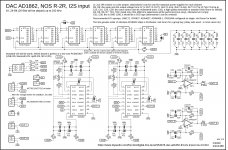
Pavel from pavouk.org took inspiration from dddac and eric juaneda projects.
dddac: DDDAC 1794 NOS DAC - Non Oversampling DAC with PCM1794 - no digital filter - modular design DIY DAC for high resolution audio 192/24 192kHz 24bit
eric juaneda from 2009: http://tech.juaneda.com/schema/ddecoder04.gif
Perhaps the train goes even deeper in the history 😛
... I used inspirations from these smart guys and added AD1862 ...
Now we are still waiting for your work - without shift registers directly from I2S ... perhaps you are smarter designer as the guys mentioned above ... and I will "sell" your idea in my thread

Last edited:
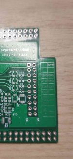
PCB v1.3 (pad)
The same as PCB v1.3 in post #1278, except:
- the Vout pin on I2S header is removed (@diyiggy)
- added pins for a direct drive without shift registers with a suitable I2S converter (break JP1, JP2) (@Vunce)
The same as PCB v1.3 in post #1278, except:
- the Vout pin on I2S header is removed (@diyiggy)
- added pins for a direct drive without shift registers with a suitable I2S converter (break JP1, JP2) (@Vunce)
Attachments
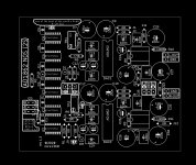

Nice, so you left connected pads so we can just scrape off if we decide to not use shift registers.... thanks 

Exactly, for direct drive just break JP1,JP2 (if shift registers are mounted).
If on initial decision it will be without shift registers (no shift register is mounted) than nothing needs to be breaked because there would be no conflict 🙂
If on initial decision it will be without shift registers (no shift register is mounted) than nothing needs to be breaked because there would be no conflict 🙂
Many thanks Miro, just one ideia, it could be made with a jumper instead cutting the traces? It is easier to test both options.. what do you think?Exactly, for direct drive just break JP1,JP2 (if shift registers are mounted).
If on initial decision it will be without shift registers (no shift register is mounted) than nothing needs to be breaked because there would be no conflict 🙂
The blob of solder is good solution.
Or cut the jumper and solder a 1.27mm pin header directly on the small pads and use a 1.27mm jumper (carefully, the pad can be fragile under mechanical stress).
855-M50-3530242
855-M50-1920005
Or cut the jumper and solder a 1.27mm pin header directly on the small pads and use a 1.27mm jumper (carefully, the pad can be fragile under mechanical stress).
855-M50-3530242
855-M50-1920005
Miro1360
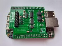
Thank you for the updated board. Sorry for being clever. Maybe there is still an opportunity for you to redo and update the post. It is not enough that the contacts are in the order DATA - BCLK - LRCK, as on the Amanero block and other transports. This implementation will give several positive points:
1. You can get rid of the wires that go from the transport to the DAC board. And clip your transport directly to the board.
2. Anyone will be able to assemble a reclocker of high quality, freely available and not expensive to manufacture.
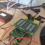
3. This reclocker is made for and works great with BBB (Beagle Bone) minicomputer, the firmware is debugged and works very well too, the firmware works with HQP, ROON, Tidal, MPD and other network services.
It is clear that this reclocker can be hooked up with wires, but this will not be due to perfectionism).
Thank you for the updated board. Sorry for being clever. Maybe there is still an opportunity for you to redo and update the post. It is not enough that the contacts are in the order DATA - BCLK - LRCK, as on the Amanero block and other transports. This implementation will give several positive points:
1. You can get rid of the wires that go from the transport to the DAC board. And clip your transport directly to the board.
2. Anyone will be able to assemble a reclocker of high quality, freely available and not expensive to manufacture.
3. This reclocker is made for and works great with BBB (Beagle Bone) minicomputer, the firmware is debugged and works very well too, the firmware works with HQP, ROON, Tidal, MPD and other network services.
It is clear that this reclocker can be hooked up with wires, but this will not be due to perfectionism).
Attachments
Last edited:
[emoji846][emoji846][emoji846][emoji106]Miro1360
Thank you for the updated board. Sorry for being clever. Maybe there is still an opportunity for you to redo and update the post. It is not enough that the contacts are in the order DATA - BCLK - LRCK, as on the Amanero block and other transports. This implementation will give several positive points:
1. You can get rid of the wires that go from the transport to the DAC board. And clip your transport directly to the board.
2. Anyone will be able to assemble a reclocker of high quality, freely available and not expensive to manufacture.
3. This reclocker is made for and works great with BBB (Beagle Bone) minicomputer, the firmware is debugged and works very well too, the firmware works with HQP, ROON, Tidal, MPD and other network services.
It is clear that this reclocker can be hooked up with wires, but this will not be due to perfectionism).
Just move to 5 PIN - DATA
for 3 PIN BCLK
and 1 PIN LRCK
well, it is advisable to move the PIN block to the middle of the side on which it is located so that the reclocker is in the middle, although it can be adjusted in this position too.
for 3 PIN BCLK
and 1 PIN LRCK
well, it is advisable to move the PIN block to the middle of the side on which it is located so that the reclocker is in the middle, although it can be adjusted in this position too.
So that something like this can be used to fasten the DAC to the reclocker
There will be a bomb! No USB, BBB is galvanically isolated from LAN and PC respectively. The firmware is cleaned up for a minimum load on the BBB, so that we feed it and we get it on the DAC.
Well, plus, people will be able to fasten Amanero, XMOS transports wirelessly.
There will be a bomb! No USB, BBB is galvanically isolated from LAN and PC respectively. The firmware is cleaned up for a minimum load on the BBB, so that we feed it and we get it on the DAC.
Well, plus, people will be able to fasten Amanero, XMOS transports wirelessly.
Attachments
Last edited:
Miro, your on fire! 😀
Since your in a “giving” mood, I’ve got another idea....
If not to much of a hassle, Maybe add SOIC8 SMD pads inside the DIP8 footprint so smd opamps can be soldered directly instead of using adapter pcb and socket.
Or just file my idea in the garbage can, LOL
Since your in a “giving” mood, I’ve got another idea....
If not to much of a hassle, Maybe add SOIC8 SMD pads inside the DIP8 footprint so smd opamps can be soldered directly instead of using adapter pcb and socket.
Or just file my idea in the garbage can, LOL
[emoji846][emoji846][emoji106][emoji106][emoji106][emoji106][emoji3]Miro, your on fire! 😀
Since your in a “giving” mood, I’ve got another idea....
If not to much of a hassle, Maybe add SOIC8 SMD pads inside the DIP8 footprint so smd opamps can be soldered directly instead of using adapter pcb and socket.
Or just file my idea in the garbage can, LOL
- Home
- Source & Line
- Digital Line Level
- DAC AD1862: Almost THT, I2S input, NOS, R-2R