hi
at post 1567
R8-R15 control the closed loop gain, a totally different thing.
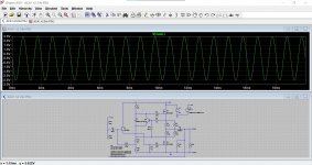
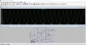
As Nelson suggested in the ACA article, I connected a series of .1 ohm resistor to replace R1-R4 with a switch to select a tap and listened to the ACA with the feedback (R12) disconnected. That's how I know it changes the open loop gain. Furthermore I found that when R3-R4 is effectively 0.82 ohm and R1-R2 is effectively 0.15 ohm, (R15 needs to be adjusted to set the quiescent current) open loop distortion is greatly reduced, on the order of 1% at 1W with the feedback disconnected. I posted a graph of this earlier in this thread. This is what leads me to the conclusion that lowering R3-R4 would increase distortion because a smaller signal would be driving Q2's Gate through C4. I can't say it sounds any better, but measured distortion is lower.
again R12 Rf disconnected..
C4??? is that a typo?? i dont understand..😕
at post 1567
R8-R15 control the closed loop gain, a totally different thing.
As Nelson suggested in the ACA article, I connected a series of .1 ohm resistor to replace R1-R4 with a switch to select a tap and listened to the ACA with the feedback (R12) disconnected. That's how I know it changes the open loop gain. Furthermore I found that when R3-R4 is effectively 0.82 ohm and R1-R2 is effectively 0.15 ohm, (R15 needs to be adjusted to set the quiescent current) open loop distortion is greatly reduced, on the order of 1% at 1W with the feedback disconnected. I posted a graph of this earlier in this thread. This is what leads me to the conclusion that lowering R3-R4 would increase distortion because a smaller signal would be driving Q2's Gate through C4. I can't say it sounds any better, but measured distortion is lower.
again R12 Rf disconnected..
C4??? is that a typo?? i dont understand..😕
Removing R1 and R3 just cuts the 'standing' or bias current in half and so limits the amps ability to drive lower impedance lowers fully. It would run cooler of course.
Removing R12 does not remove all the feedback, it just removes a big chunk.
There is another feedback path effectively in parallel with R12 consisting of R10 and the variable and unknown quantity of the preset.
The gain with R12 removed jumps from around 11.3db (no load attached) to around 36db. I think the performance would be pretty shocking run like that because the open loop gain of the ACA is so low anyway that now you would find adding a normal load severely affects the output. Add a load like a real speaker (such as my B&W) and the response would be like looking at the Himalayas. It would be bad beyond belief like that.
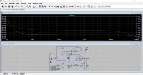
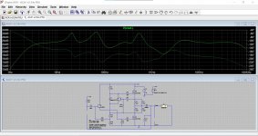
In fact... this is how bad. This is with and without an 8 ohm load resistor. R12 removed.
Look at the difference in output amplitude as the load is removed. Now imagine a speaker that goes from say 3 ohms to perhaps 30 ohms over the audio bandwidth. The response would be awful.
So don't remove R12 😉
Removing R12 does not remove all the feedback, it just removes a big chunk.
There is another feedback path effectively in parallel with R12 consisting of R10 and the variable and unknown quantity of the preset.
The gain with R12 removed jumps from around 11.3db (no load attached) to around 36db. I think the performance would be pretty shocking run like that because the open loop gain of the ACA is so low anyway that now you would find adding a normal load severely affects the output. Add a load like a real speaker (such as my B&W) and the response would be like looking at the Himalayas. It would be bad beyond belief like that.
In fact... this is how bad. This is with and without an 8 ohm load resistor. R12 removed.
Look at the difference in output amplitude as the load is removed. Now imagine a speaker that goes from say 3 ohms to perhaps 30 ohms over the audio bandwidth. The response would be awful.
So don't remove R12 😉
Attachments
hi
at post 1567
R8-R15 control the closed loop gain, a totally different thing.................
One for tomorrow 🙂
According to the post #861 page 87
https://www.diyaudio.com/forums/pass-labs/215392-amp-camp-amp-aca-87.html#post3427257
....If Q4's Idss is less than 4.5mA, it's Gate to Source voltage would go positive before there is enough Gate voltage at Q1. So a Toshiba GR grade part (Idss 2.0 to 6.5mA) might not work in the circuit as designed...
can that be that my K30A is too weak to get enough current ? i looked at my K30A the have labeled GR...but not as written in the datasheet 035G...so its a different version and that is the bad i guess
a 330k resistor adjusts the gate bias of the input jfet so that the gain mosfet gets biased to get its drain voltage to 1/2 b+, as long as this can happen, then there is nothing to be concerned about...
the ACA is such a simple circuit, no point in trying to overthink it...just enjoy the music.
this is one such amplifier that once you stuff in all the parts correctly, mount on a heatsink properly.....and after adjusting the output node for 1/2 b+ will work immediately...
Last edited:
oh yes...i got a lot to rad and learn
thx
you can read up on Walt Jung's OpAmp Cookbook....
.................... I can't say it sounds any better, but measured distortion is lower.[/I]
again R12 Rf disconnected..
C4??? is that a typo?? i dont understand..😕
Quick question 🙂
An easy one to start the day. Are you using Firefox? If so then try this to stop this.
Attachments

Removing R1 and R3 just cuts the 'standing' or bias current in half and so limits the amps ability to drive lower impedance lowers fully. It would run cooler of course.
Removing R12 does not remove all the feedback, it just removes a big chunk.
There is another feedback path effectively in parallel with R12 consisting of R10 and the variable and unknown quantity of the preset.
The gain with R12 removed jumps from around 11.3db (no load attached) to around 36db. I think the performance would be pretty shocking run like that because the open loop gain of the ACA is so low anyway that now you would find adding a normal load severely affects the output. Add a load like a real speaker (such as my B&W) and the response would be like looking at the Himalayas. It would be bad beyond belief like that.
In fact... this is how bad. This is with and without an 8 ohm load resistor. R12 removed.
Look at the difference in output amplitude as the load is removed. Now imagine a speaker that goes from say 3 ohms to perhaps 30 ohms over the audio bandwidth. The response would be awful.
So don't remove R12 😉
ok Molly. i understand.
to be honest the creator do something:
did you think Loudthud do not try to check/ listen to his changes?
Quick question 🙂
An easy one to start the day. Are you using Firefox? If so then try this to stop this.
yes you are right. its my setup...i am just have to find it where this setting exist
I think any such changes can sometimes be perceived as not only different but sometimes 'better'. Its a really personal thing, like altering the tonal balance.
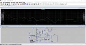
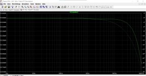
This really shows the effect. Four images, the first with an 8 ohm load, the second with the speaker load and 39k and then with the feedback removed. The final image is another amplifier (most solid state amps and chip amps are like this one) driving the speaker load.
You are looking at the output of the ACA vs frequency. The resistive load does not alter anything, the speaker load impedance pulls and pushes against the output giving the really uneven response seen.
So in part the high output impedance of the ACA, its low open loop gain and the fact that the output gets modified by the load is all part of its charm and gives it its unique qualities.
Attachments
yes you are right. its my setup...i am just have to find it where this setting exist
I'm afraid I don't where that lives as I use Edge but your line spacing has got noticed over many months. I think someone else has been following some of your posts and tweaking them (not me 😉)
Type about:config into the address bar (same place you type http://www....). Then search for newlineswhere this setting exist
Sorry, C2 drives Q2's Gate. My speakers have a simple 6dB/Oct crossover with a zobel on the woofer and L-Pad on the tweeter. Very flat impedance plot. The output impedance of the ACA is significant even with feedback, so if your speakers have wild impedance changes, the ACA may not be for you.
I have a small question, I would like to build 4 ACA channels in one box and use XLR or RCA inputs. In the build guide (1.6) is stated that if you use the ACA1.6 as a mono box with balanced inputs the switch on the back should be down, and if you use the amp as a mono box with the rca input the switch should be up.
If the switch is in the up position, can't the amp be used with the XLR input?
so the short question is... do i need switches? 🙂
Cheers, Neel007
If the switch is in the up position, can't the amp be used with the XLR input?
so the short question is... do i need switches? 🙂
Cheers, Neel007
Last edited:
Sorry, C2 drives Q2's Gate. My speakers have a simple 6dB/Oct crossover with a zobel on the woofer and L-Pad on the tweeter. Very flat impedance plot. The output impedance of the ACA is significant even with feedback, so if your speakers have wild impedance changes, the ACA may not be for you.
Hi

i want to understand and follow what some expert mentioned here...😉
i guess my impedance is not really wild but the nominal impedance of 4R is not easy for ACA.
chris
Yes, you are not wrong:
"i guess my impedance is not really wild but the nominal impedance of 4R is not easy for ACA."
ACA is not very happy with 4R, no matter how well behaved the impedance is.
ACA loses control rather quickly and the end result is not pretty.
Possible solutions:
1. Build 8R, high SPL (92dB +) speakers to mate with ACA.
2. Build a different amp to work with your current speakers - MoFo will be a good match, provided your preamp can supply enough juice to it.
2A. Build F5 or M2(M2X) and use your existing preamp.
3. This is just the beginning of the game that never ends.
Hi Stanislav
before i give up to try to ACA i will change my speakers to my open baffle. 12" /W5. as i showed in my first posts. BPA Dipol 12"/5 and i changed the 5" to W2143 (bamboo). and the lower sub is off -so i get a 8R speaker.
source juice is hopefully enough - i go directly from my DAC - Gustard A20H to my power amps...i used the preamp function to get enough power over RCA into ACA
yes a big Class A is the my plan...but first enjoy the small amps ..
chris
Hi Chris,
Sorry if I caused some confusion, I did not say give up trying ACA.
As a matter of fact ACA is and has been my main amp for the last 5-6 years, driving a number of speakers, from 2way MTM vented (4R), 2way MT Aperiodic, 3way MLTL+Aperiodic Mid, and now a 3way Aperiodic+OB mid.
All with 1st order series xovers.
With a lot of mods both for the speakers and for ACA in between.
Because I like the way the ACA sounds.
I also run a MoFo in another room with the first set of speakers and a tube pre, but I prefer the ACA, especially with the latest incarnation of my speakers.
I guess it has something to do with the Single ended nature of ACA.
And I'll share a little secret here:
my next amp (which is almost ready) is ACA with 44V supply, similar to Tony Tecson's. That will be something.
Last edited:
Short answer is Yes. ;-)I have a small question, I would like to build 4 ACA channels in one box and use XLR or RCA inputs. In the build guide (1.6) is stated that if you use the ACA1.6 as a mono box with balanced inputs the switch on the back should be down, and if you use the amp as a mono box with the rca input the switch should be up.
If the switch is in the up position, can't the amp be used with the XLR input?
so the short question is... do i need switches? 🙂
Cheers, Neel007
XLR supplies both 'sides' in full balanced mode.
RCA balanced is a pseudo balanced mode. It takes the output of the white 'side' and feeds it to the input of the red 'side' through the resistor switch combination.
If you try XLR with the resistor in place the red side gets 2 very slightly different input signals.
Alan
I have a small question, I would like to build 4 ACA channels in one box and use XLR or RCA inputs.
Do you need to operate 4 speakers/4 channels and/or are you using a balanced source and want to have monoblocks for 2 channels? Do you have a single-ended source with only RCA outputs and still want to bridge the amps?
so the short question is... do i need switches? 🙂
Cheers, Neel007
You would want the switch if you ever wanted to bridge the amps using a single-ended source and use an RCA connection. If you only intend to use it with a balanced source through XLR as a monoblock or stereo RCA, then no. Either way, if you chose to wire it w/o a switch, then you will not want it wired in the "switch up" position. You will want it wired like the "switch down" position.
If the switch is in the up position, can't the amp be used with the XLR input?
Short answer, maybe...???? But I wouldn't. Why?
See the wiring guide for 1.6 step 33. You would be:
- feeding the inverted signal from pin 3 through one amp board
- the signal would be amplified and phase inverted to positive phase and the signal would include the distortion from the amplification
- the voltage would be reduced through the 39k resistor,
- then it would be combined with the "non-distorted" positive phase input from pin 2 and amplified through the other amp board to which you would hook up your speaker.
If you wired your speaker properly to just that amp board (NOT like you would for 'Normal' XLR bridged operation), it probably would not hurt anything. I'm not sure how that would sound. Also, you'd be feeding the signal at 'double' the voltage to one amp board. Depending on the level, you'd probably clip much more easily.
Someone else should proof this for accuracy to be certain. I could be way off, but there's a small chance I have some of it correct.
Edited to add: See above for a much more simple answer. I type too slowly. 😀
Last edited:
- Home
- Amplifiers
- Pass Labs
- Amp Camp Amp - ACA