Question for Sir David =)
So I've been going from the loudspeaker wizard Fr screen> f9 to export magnitude and phase> import into Vituix and exporting the IR> Import into REW to review data.....
I recently wanted to compare IR's at different volumes...following the same process, I was sucecssfull for my offset horn with rear chamber...I have a comparable design expressed as a compound horn, in order to add damping to vented rear chamber...though it turns the offset horn in to a front lopaded horn...I work with it....
My issue/question is regarding the two different end results I get from 1watt vs what I get from placing 30hz at 115db for my comparison....unlike the first enclosures compared at different volumes, my compound horn final IR looks about identical to each other.....the decay figures are almost identical too....
Just wondering what was up with that....I could try this experiment with offset horn and vented rear chamber but then I can't keep damping in the equation....my guess is this might have something to do with the same reason why HornResp won't "calculate" with damping in the equation....
Looking at what I import into Virtuix. the phase between the two versions (1watt vs 115@30hz) is identical. I tried two different IR's generated from Hornresp for a vented design at two different volumes and the IR's identical as well.
Thanks in advance.
Last edited:
Hi,
Now I am here again. Trying to fit a ML-TL in a already built Rauna concrete cabinet.
Mixing different drivers and "save" from Loudspeaker wizard, and answer Yes when it ask me if i want to save the records when starting a new design. Despite that nothing is saved. What do I do wrong??????? I mean, how could I fail to do something as simple as save a design????😀
I have had this happen a fair bit - but not all the time. It feels like a bug?
That "Hornresp is a virus?" question gets asked so much that maybe David you should put a notice on the download site to tell potential downloaders that there's nothing wrong with the program 🙂
That's because the two systems are different 🙂.
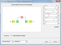
Try comparing the acoustic circuit diagrams - the one for BP6P is attached.
The acoustic circuits are a bit different, but in terms of topology the models are pretty close, so I expected the sim results to be pretty close. However the BP sim puts a pretty big dip in the middle of the passband that does not show up in the TH sim.
FWIW, measurements show that the TH sim is the more accurate one, even though it doesn't take the impact of the offset driver in Vrc into consideration.
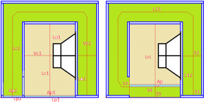
I've attached a diagram showing how the sims were created. Yes, I moved the vent a little - I didn't expect moving it from the edge of the mouth to just outside the mouth would make such a big difference in the middle of the passband. I guess it would be more accurate to model it as a series-tuned 6th order system, but Hornresp doesn't provide a means to model an offset rear vent.
Attachments
Hi, I'm new to Hornresp but i have problem to install it on WIN10...because WIN recognize a virus in Hornresp.exe.
I downloaded Hornresp from Hornresp .... Does someone have the same problem?
thx
I think this happened when I first ran it, as well. You can click the little button on the security dialog that says More Info - and then you can say Run Anyways, and it should run.
What do you think, despite the co-location constraint on two of the outputs, would this additional functionality be worth including?
If it's fairly easy to do, yes. I suspect that driver and co-located vents would be close enough for sim purposes for most uses.
My issue/question is regarding the two different end results I get from 1watt vs what I get from placing 30hz at 115db for my comparison
The differences you refer to, are they in the Hornresp results or in the results produced by VituixCAD / REW using exported Hornresp data?
If in the Hornresp results, please provide further specific information (screenprints of inputs and outputs, and what differences are concerning you).
If in the VituixCAD / REW results, unfortunately I cannot help you, as I have not used either of those software packages.
maybe David you should put a notice on the download site to tell potential downloaders that there's nothing wrong with the program 🙂
I don't know about you, but if I saw a message like that on a website I am not sure that I would believe it anyway. If anything, it would probably just make me more suspicious... 🙂.
I have had this happen a fair bit - but not all the time.
Everything seems to be working just fine for me. Are you following the sequence of events detailed in Post #11416? If not, what are you doing differently that is causing the problem?
If indeed there is a bug the only way that I can fix it is by being able to reproduce it myself. To do this I will need more specific information.
I've attached a diagram showing how the sims were created.
I am having trouble interpreting the diagram 🙂.
The Hornresp input parameters for the two 'equivalent' systems would be more helpful for me...
I'm new to Hornresp but i have problem to install it on WIN10...because WIN recognize a virus in Hornresp.exe.
See Post #11419.
If it's fairly easy to do, yes.
It will be in the next update.
I am having trouble interpreting the diagram 🙂.
The Hornresp input parameters for the two 'equivalent' systems would be more helpful for me...
They're in the BOXPLAN-PARAC workbook, in two hidden spreadsheets called "HORNRESP (BP6P) and "HORNRESP (TH)". The workbook isn't password-protected, so the sheets can be unhidden.
The differences you refer to, are they in the Hornresp results or in the results produced by VituixCAD / REW using exported Hornresp data?
If in the Hornresp results, please provide further specific information (screenprints of inputs and outputs, and what differences are concerning you).
If in the VituixCAD / REW results, unfortunately I cannot help you, as I have not used either of those software packages.
That was my mistake, I miss labelled a file, thought I had tapped into some undiscovered aspect of Horn Resp lol. Sorry about that.
I've been using your program to study low tuned vented designs....a low tuned stuffed vent seems to be a worthy alternative to a sealed stuffed box.... for me to have enough confidence to attempt to build I need to understand how you intend damping to work. I aksed this before and the answer was straight forward but I feel like I need to ask again...so my Density material
RockBoard® 80 is expected to have an air flow resistivity of ~53,000 – 57,000 mks rayls/m – also Comfortboard™80
So for my compound horn (slot up front- vented rear)...I set fr1 segment1 to 53000 and if tal1 is anything but 0 it says fr1 is too big....if I set fr to 53000 for a sealed chamber...it works out...It lets me set fr1 segment 3 to 53000...so it must have something to do with the larger CSA of Segment 1 vs segment 3?...what did I do wrong?
53000 seems to make sense in what I see happen with a seal chamber but vented...I'm getting really strong results from 1% within just one small segment, which might equate to 0.22 material height in only a few inches of the line? IS it simulating a piece material stretching the csa? Maybe thats whats going on....
Last edited:
However the BP sim puts a pretty big dip in the middle of the passband that does not show up in the TH sim.
This is partly due to internal end corrections in the BP6P simulation model increasing the effective lengths of the port tubes. Other differences in the results are due to the basic system models / topologies not being exactly the same.
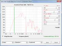
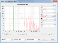
Attachment 1 shows the TH response.
Attachment 2 shows the BP6P response.
Attachment 3 shows the BP6P response with port tube internal end corrections removed.
Attachment 4 shows the TH acoustic model.
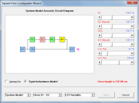
Attachment 5 shows the BP6P acoustic model.
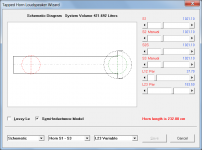
Attachment 6 shows the TH schematic diagram.
Attachment 7 shows the BP6P schematic diagram.
Attachments


I set fr1 segment1 to 53000 and if tal1 is anything but 0 it says fr1 is too big....if I set fr to 53000 for a sealed chamber...it works out
In the first case (Fr1) the material is being used as absorbent filling, whereas in the second case (Fr) it is being used as acoustical lining.
The absorbent filling material model, while a very good one, can sometimes break down mathematically at high resistivity values, depending upon the circumstances (over-flows and under-flows are generated in the calculations - there is nothing that can be done about this). This is why there may sometimes be limits imposed on the input values that can be specified.
Acoustical lining uses a completely different model, but unfortunately it is not applicable to the absorbent filling material case.
Last edited:
When TH mode in engaged a few things change. it seems to be the activity between taps is given a much greater value in its affect on response. But as L45 grows longer it suddenly is ‘compound’ Horn in its reaction (similar maybe))and also if that is used in a rear vented chamber instead it is some similar action but if you look at unwrapped phase theres a really neat thing occuring and the added length of an otherwise tapped horn with these extras is staggered at harmonics til 100x over and over the cycle.
while im Used to what occurs mostly, as the same driver consistently, is there a fraction or multiplier engaged to the parts of OD, thats then a back wave for TH also? A guideline or similar to grab a firm understanding of probably the most interesting and challenging horn layout and creation if i was trying to pick to date (ME still left).
while im Used to what occurs mostly, as the same driver consistently, is there a fraction or multiplier engaged to the parts of OD, thats then a back wave for TH also? A guideline or similar to grab a firm understanding of probably the most interesting and challenging horn layout and creation if i was trying to pick to date (ME still left).
I am having trouble interpreting the diagram 🙂.
The Hornresp input parameters for the two 'equivalent' systems would be more helpful for me...
Maybe this is helpful...

And measurement 0cm from mouth:

Last edited:
- Home
- Loudspeakers
- Subwoofers
- Hornresp