Off Topic: CNC control PC milled with mini cnc
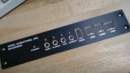
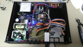
Thimios: a small HIFI2000 case and front panel has been milled to carry the mini cnc OS running on a raspberry pi4 4GB. Inside:
Thimios: a small HIFI2000 case and front panel has been milled to carry the mini cnc OS running on a raspberry pi4 4GB. Inside:
- 12V/60W power supply
- passive cooled rpi4 + diy milled control board
- 12V to 5V converter for rpi4
- 12 V output for a lubricant pump.
- 12 V output for a electro-pneumatic valve to control cooling lubricant
- 230V switched output to control vacuum cleaner
Attachments
SA2021 New Class H Prototype working
SA2021 New Class H Prototype working like a charm.
Fixed missing capacitor for low voltage rails. Added a 1000uF per low voltage rail input.
Now it's time to increase the high voltage up to 80V for power tests.
The 20k THD+N doesn't change significant during takeover to high voltage rail - the tests was done with +/- 20V low voltage rail and +/- 31V high voltage rail.
The THD+N 20kHz stays below 0.006% up to 18.8V RMS on 8R load.
The first watt 20k THD+N is 0.0019%
Bias is 240mA total (120mA per TTC/TTA pair).
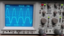
At the scope you can see the output and below the gate voltage at p-channel mosfet IXTH48P20. Clipping behavior is like SA2014.
I'm very impressed about the good performance. The simulation predicted such good values, but if the real world results are the expected ones, it is always a good day for drinking beer - cheers

Well done DaveZan and Astx! 😀
More test data will follow.
Have fun,
BR, Toni
P.S.: the attached input stage is the original SA2014 ips/vas pcb as you can see.
SA2021 New Class H Prototype working like a charm.
Fixed missing capacitor for low voltage rails. Added a 1000uF per low voltage rail input.
Now it's time to increase the high voltage up to 80V for power tests.
The 20k THD+N doesn't change significant during takeover to high voltage rail - the tests was done with +/- 20V low voltage rail and +/- 31V high voltage rail.
The THD+N 20kHz stays below 0.006% up to 18.8V RMS on 8R load.
The first watt 20k THD+N is 0.0019%
Bias is 240mA total (120mA per TTC/TTA pair).
At the scope you can see the output and below the gate voltage at p-channel mosfet IXTH48P20. Clipping behavior is like SA2014.
I'm very impressed about the good performance. The simulation predicted such good values, but if the real world results are the expected ones, it is always a good day for drinking beer - cheers
Well done DaveZan and Astx! 😀
More test data will follow.
Have fun,
BR, Toni
P.S.: the attached input stage is the original SA2014 ips/vas pcb as you can see.
Attachments
Last edited:
Thimios: a small HIFI2000 case and front panel has been milled to carry the mini cnc OS running on a raspberry pi4 4GB. Inside:
BR, Toni
- 12V/60W power supply
- passive cooled rpi4 + diy milled control board
- 12V to 5V converter for rpi4
- 12 V output for a lubricant pump.
- 12 V output for a electro-pneumatic valve to control cooling lubricant
- 230V switched output to control vacuum cleaner
Excellent work as usual!SA2021 New Class H Prototype working like a charm.
Fixed missing capacitor for low voltage rails. Added a 1000uF per low voltage rail input.
Now it's time to increase the high voltage up to 80V for power tests.
The 20k THD+N doesn't change significant during takeover to high voltage rail - the tests was done with +/- 20V low voltage rail and +/- 31V high voltage rail.
The THD+N 20kHz stays below 0.006% up to 18.8V RMS on 8R load.
The first watt 20k THD+N is 0.0019%
Bias is 240mA total (120mA per TTC/TTA pair).
At the scope you can see the output and below the gate voltage at p-channel mosfet IXTH48P20. Clipping behavior is like SA2014.
I'm very impressed about the good performance. The simulation predicted such good values, but if the real world results are the expected ones, it is always a good day for drinking beer - cheers
Well done DaveZan and Astx! 😀
More test data will follow.
Have fun,
BR, Toni
P.S.: the attached input stage is the original SA2014 ips/vas pcb as you can see.
That's why i wish to have a mini cnc!😉
Nice work to your new amplifier too!😎
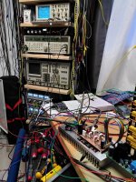
A very nice laboratory!!!
Congratulations Toni!
I have SA2014 ips/vas pcb.May be it is time try to populate those.
What is the Pi4 dac?
Thx!
The only difference to the passive cooled RPI4 shown at the picture vs the link is, I have used a pentium heatsink instead of a ct-54 heatsink
BR, Toni
If you mean the RPI4 between amp and measurement tower: this is no RPI4 DAC hat - it is my selfdesigned RTC, console, power on/off switch hat.... What is the Pi4 dac?
The only difference to the passive cooled RPI4 shown at the picture vs the link is, I have used a pentium heatsink instead of a ct-54 heatsink
BR, Toni
Last edited:
Thanks Toni.
Very interesting solution for Rpi power on-off without unplug the power supply.
Are files ,pcb & schematic for share?
I can't see the hat dac😕
Nice passive cooler!
Very interesting solution for Rpi power on-off without unplug the power supply.
Are files ,pcb & schematic for share?
I can't see the hat dac😕
Nice passive cooler!
Last edited:
Dear Thimios,
the RPI4 is from a different project and has no DAC hat attached!
Unfortunately the power on/off, console, rtc pcb is a commercial project. Maybe I can share it in a few years.😱😉
If you need a pcb, send me a pm or email.
BR, Toni
the RPI4 is from a different project and has no DAC hat attached!
Unfortunately the power on/off, console, rtc pcb is a commercial project. Maybe I can share it in a few years.😱😉
If you need a pcb, send me a pm or email.
BR, Toni
The pro using this Class H rail tracker is:
- Very low THD increase during the smooth transition from the low to high voltage rail because the inner power transistors have mostly constant Vce up to HV rail.
- The power dissipation happens mostly on the outer power transistors which in this case are high power V-MOSFETs. 2 of them can e.g. dissipate a maximum of 1000W!
- The inner transistors can have high bias to get the first watts in Class A without dissipating too much power.
- The boot strapping of the MOSFET gate voltage allows to use the full HV rail voltage. Clipping starts at < 3V difference to HV voltage.
Hi Astx,
Will this work with +-90Vdc (high rail) and +-45Vdc (low rail) supply?
thanks,
Roland
Will this work with +-90Vdc (high rail) and +-45Vdc (low rail) supply?
thanks,
Roland
Theoretically yes. But some resistors need to be recalculated.
Of course using higher LowerRailVoltage (LRV) the idle power dissipation will increase without positive effects. The final Amplifier will be equipped with 4 TTC/TTA pairs and hence the total idle bias is about 500 - 600mA. Setting the LRV higher as 20V is IMHO unnecessary waste of energy.
BR, Toni
Of course using higher LowerRailVoltage (LRV) the idle power dissipation will increase without positive effects. The final Amplifier will be equipped with 4 TTC/TTA pairs and hence the total idle bias is about 500 - 600mA. Setting the LRV higher as 20V is IMHO unnecessary waste of energy.
BR, Toni
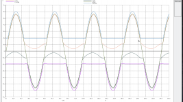
SA2021 New Class H Prototype - Measurements
... now we have +/- 62V HRV and +/-20V LRV ...
Attached simulation using ngspice vs real word measurements.
The scope pictures Gate voltage is not exactly aligned on the y axis!
The shown waveform is exactly as the simulated one.
Measured 20k THD+N bw 80kHz is about 0.0019% using 8R load
Output noise:
... now we have +/- 62V HRV and +/-20V LRV ...
Attached simulation using ngspice vs real word measurements.
Code:
Fourier analysis for output:
  No. Harmonics: 10, THD: 0.00240604 %, Gridsize: 500, Interpolation Degree: 1

Harmonic Frequency Magnitude Phase     Norm. Mag Norm. Phase
-------- --------- --------- -----     --------- -----------
 0       0         -0.0136   0         0         0
 1       2e+04     56.33     -2.56     1         0
 2       4e+04     0.000825  134.5     1.464e-05 137.1
 3       6e+04     0.0003591 -173      6.374e-06 -170
 4       8e+04     0.0004111 13.43     7.298e-06 16
 5       1e+05     0.0004215 171.9     7.483e-06 174.5
 6       1.2e+05   0.0003035 -20.6     5.388e-06 -18
 7       1.4e+05   0.0004832 127.1     8.577e-06 129.6
 8       1.6e+05   0.0003059 -62.6     5.43e-06  -60
 9       1.8e+05   0.0005116 95.96     9.081e-06 98.52

LRail      power : 5.67535 W
HRail      power : 328.838 W
Total      power : 334.513 W
Output     power : 198.315  W
Power dissipation: 136.197 W
#---------------------------------------------------------------------
# loopgain results for plot ac3
#---------------------------------------------------------------------
GM : -21.9729
PM : -106.288
3db : 2.27938E+07
0db : 2.71911E+06
  dc gain : 116.629
The shown waveform is exactly as the simulated one.
Measured 20k THD+N bw 80kHz is about 0.0019% using 8R load
Output noise:
- full bw 132uV
- 80k bw 60uV
- 20k bw 33uV
- A-w: 20uV
- 11 0dB full bw
- 116 dB 80k bw
- 122 dB 20k bw
- 125 dB A-w
- 86 db ful bw
- 94 dB 80k bw
- 98 dB 20k bw
- 102 db A-w
Attachments
Last edited:
Nice!
Simulation & real world close enough!
I have a piece of double sided photoresist board left somewhere.
If the board pattern will be available as pdf ,or gerbers....😉
Simulation & real world close enough!
I have a piece of double sided photoresist board left somewhere.
If the board pattern will be available as pdf ,or gerbers....😉
Thx!
This is not the final release! Only to test the idea.
The amplifier is in development for 4-8 pairs TTC/TTA and 2-4 pairs IXYS mosfet...
This is not the final release! Only to test the idea.
The amplifier is in development for 4-8 pairs TTC/TTA and 2-4 pairs IXYS mosfet...

What about microcontroller based amplifier overcurrent/soa/temperature/dc protection using rail current sensor like TMCS1100? Any reference implementation made?
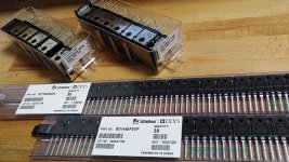
SA2021 New Class H Prototype - Parts / Ideas
Important parts arrived today - a lot of IXYS V-Mosfets.
New and relatively cheap hall sensors made me think about a new variant of amplifier SOA protection which doesn't have an impact on sound quality:
BTW - Index in first post has been updated ... are you something missing there?
BR, Toni
Important parts arrived today - a lot of IXYS V-Mosfets.
New and relatively cheap hall sensors made me think about a new variant of amplifier SOA protection which doesn't have an impact on sound quality:
Scan current, voltage and heatsink temperature of the power Mosfets/BJTs and calculate SOA using a microcontroller. A fast enough microcontroller can do this several 10k times a second. On overload condition switch of the input (audio relais) and/or power down the amplifier.
Whats your opinion?
BTW - Index in first post has been updated ... are you something missing there?
BR, Toni
Attachments
Yes i think that is time for a protection update!
Today many new products existing
Many options,especially when you can write the software(code).
No relaies but SSR😉
Today many new products existing
Many options,especially when you can write the software(code).
No relaies but SSR😉
I am strictly against an MCU protection circuit. A protective circuit must be as simple as possible. Less complexity, greater reliability. An MCU can go crazy at any time.
It depends on the software complexity...
A classical current limiter adds some distortions many don't want ...
A classical current limiter adds some distortions many don't want ...
Last edited:
At input signal levels a ssr is adding too much distortions. Even using some of the best JFETS to short the input signal adds unwanted distortions in normal operating mode ......
No relaies but SSR😉
- Home
- Amplifiers
- Solid State
- 2stageEF high performance class AB power amp / 200W8R / 400W4R