Eli,
I see the point of adding a source follower in between, and it is very logical. Since it's a unity voltage gain buffer, I believe it won't affect the sound quality downwards right? Instead, it will create a high input low output buffer in between I/P and O/P stage, helping the triode to drive the output stage.
jjman,
Thank you for sharing it 🙂 You've mentioned an important thing here: choke vs resistor. I will consider both when I get to design the PS.
@aerenyasar
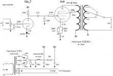
The key to selecting a FET for source follower duty in hybrid circuitry is finding a part whose reverse transfer capacitance (Crss) is small and "stable". When Crss is too large, high frequency information is lost via the grounded drain electrode. At 4 pF., the ZVN0545A meets the requirement. Even wimpy types, like the 12AX7 and EF86, have no problem with that. FWIW, my favorite FET for use with tube types that have some "grunt" is the IRFBC20. That part's Crss is also favorable.
Experience shows that a protective Zener diode must be installed between the gate circuitry and the source electrode. Power on transients are present, given FETs turn on "immediately" and thermionic emission/tube conduction takes some time to begin.
I suggest you read MOSFET Follies. Plenty of good info. on that page.
The key to selecting a FET for source follower duty in hybrid circuitry is finding a part whose reverse transfer capacitance (Crss) is small and "stable". When Crss is too large, high frequency information is lost via the grounded drain electrode.
At 4 pF., the ZVN0545A meets the requirement. Even wimpy types, like the 12AX7 and EF86, have no problem with that. FWIW, my favorite FET for use with tube types that have some "grunt" is the IRFBC20. That part's Crss is also favorable.Experience shows that a protective Zener diode must be installed between the gate circuitry and the source electrode.
Power on transients are present, given FETs turn on "immediately" and thermionic emission/tube conduction takes some time to begin.I suggest you read MOSFET Follies. Plenty of good info. on that page.
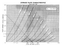
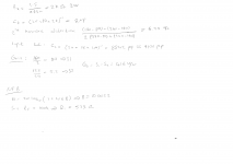
Today, I've tried to design the rest of the amplifier (except the PS). I'm attaching my loadline for 12AX7, calculations and overall schematic. I've removed the grid potentiometer at the output. I'm not sure whether to leave it or not. I've recalculated the NFB attenuation for current gain. I'd be happy to hear any feedbacks.
PS: In schematics, B+2 is 300V and B+1 is 250V.
PS: In schematics, B+2 is 300V and B+1 is 250V.
Attachments
Last edited:
@aerenyasar
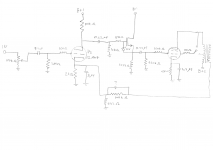
I revised the signal schematic. Neaten my poor "hen scratches".
Most of the time, exceeding 100 Kohms of grid to ground resistance with the 'X7 triode is a bad idea, lest CMiller interact and cause HF info. loss. 😡 Modern, commercial, digital signal sources must be capable of driving the 10 Kohm IHF "standard" load. Therefore, a 10 Kohm log. taper volume control is fine.
The source follower is DC coupled to the triode's plate, which makes the forward bias requisite for enhancement mode devices, like the ZVN0545A, automatic. 🙂 Size the FET's source load resistor to make ID = 2 mA. The calculation is easy, as the source follows the gate and the gate is at the same potential as the triode's anode. 😉
BTW, tube control grid and FET gate stopper resistors should be carbon composition (CC). CC resistors are both non-metallic and non-inductive. While CC parts can drift in value and be noisy, in this role those factors are unimportant. CC noise is current related and the current in these situations is vanishingly small. The exact value of a stopper resistor is very rarely critical, once it is at an appropriate level. "Taller" stoppers go hand in hand with increasing transconductance.
Attachments
Can't get that much wattage out of a single 6V6. A pair in push pull gets you about 14 watts, max.
Eli,
Thank you for your review! I'm now working on a power source. I'll use PSUD2 for determining the values. I'm planning to use a diode rectifier with a no-tap power transformer. What should I consider while choosing a power transformer? We've got 220V powerline voltage here.
One other thing is, when using diodes, can I use resistors instead of chokes and compensate it with larger shunt capacitors? If not, what should I consider while choosing the choke?
Eliminating a choke in the B+ supply will do these things:
Reduce the cost
Make the amplifier weigh less
Reduce possible magnetic interference (chokes have magnetic fields). So just space the choke away from the output transformer, and orient the choke and output transformer by 90 degrees to each other.
But . . .
You have to use more capacitance, and high wattage resistors, in order to get the same ripple from the power supply (and the voltage drop in the resistors is larger than that of the DCR of the choke). Or else, using a resistor with the same resistance as the choke DCR, you have to use even more capacitance, to get the ripple down.
And . . . more capacitance load will make the transformer primary get more hot.
It is all a tradeoff.
The NFB has two issues that need to be addressed:
- the 8uF cap on the input tube cathode shorts the NFB to ground. You can take it out, or put another resistor under the Rk//8uF and connect the NFB there. Recalculate the total R for the desired current.
- the 523 ohm resistor is in parallel to the 2k R giving an effective 415 ohm cathode resistor.
Thank you for mentioning that Parafeed, it's a big mistake I've missed over there. I'll try to solve it as you've suggested.
Summer, indra, I've found a 10$ choke, maybe I might consider to buy it. It is cheaper than I expected. I'm not sure if I want the input transformer to get hot.
About the power transformer, I2m still not sure what I should check. I've seen some transformers on DigiKey for 240V but not sure about them. One thing I've notices is they generally specify the second voltage, but since I need one high voltage and one 6V line for heaters, how can I choose the transformer?
Last edited:
As 6A3sUMMER stated, the waves spread across the pond's surface.
Large valued cap. I/P filters generate "hash", while suppressing the ripple fundamental. 🙁 Apply Fourier's Theorem to the "spikey" high current charging pulse waveform.
An (IMO) excellent compromise among size, weight, and cost that yields high B+ PSU performance is a well executed "full wave" voltage doubler setup. A 100 mA. supply is plenty for this project. Triad's N-68X is "perfect" for the job. 2X of this part in the doubler stack will "crush" ripple, but "hash" is present. Elephants are eaten 1 bite at a time. Follow the doubler with a LC section made from a high current RF choke and a 1000 pF. mica or C0G/NP0 ceramic cap., to suppress high order ripple overtones that could sneak into the rail via an "ordinary" filter choke's winding capacitance. Follow the "hash" filter with a LC reservoir section made from a Triad C-7X choke and a 120 μF. 'lytic.
Attachments
2X of this part in the doubler stack will "crush" ripple, but "hash" is present. Elephants are eaten 1 bite at a time. Follow the doubler with a LC section made from a high current RF choke and a 1000 pF. mica or C0G/NP0 ceramic cap., to suppress high order ripple overtones that could sneak into the rail via an "ordinary" filter choke's winding capacitance. Follow the "hash" filter with a LC reservoir section made from a Triad C-7X choke and a 120 μF. 'lytic.
Hey Eli -- I like the idea of the 'LC hash filter'. What specification does the hash filter choke need to meet? How much inductance is necessary? Just a couple hundred microhenries? Or more? How much current capability? A couple amperes? Or just the 100 or so milliamps drawn by the audio circuits?
--
You want "lots" of inductance, without lots of winding capacitance. Adequate current handling capability is also necessary. The list of practical choices is pretty small, as the parts are dealing with RF. Look here, for some possibilities.
Would a 512uH toroid with DCR of 0.02 ohm be useful?
It's this one:
512uH Coil
I have a couple of those. They're pretty chunky coils, about 2" in diameter, 1" high. The magnet wire is 12AWG. I think these inductors are rated for 20A, which is way overkill. They're rated for up to 150kHz. I'm hoping they're close enough to use for an LC hash filter after a SMPS or a voltage doubler. Or maybe a CLC filter for a +6V DC heater supply.
Last edited:
Would a 512uH toroid with DCR of 0.02 ohm be useful?
It's this one:
512uH Coil
I have a couple of those. They're pretty chunky coils, about 2" in diameter, 1" high. The magnet wire is 12AWG. I think these inductors are rated for 20A, which is way overkill. They're rated for up to 150kHz. I'm hoping they're close enough to use for an LC hash filter after a SMPS or a voltage doubler. Or maybe a CLC filter for a +6V DC heater supply.
IMO, those coils are better than nothing, but far from good. You're "leaning" heavily on the cap. part of the "hash" filter. Perhaps increasing to 1500 pF., like this or this, is indicated.
Happy new year everyone! After a few days of off, I've came back to work on the project. I'll update the problem mentioned by Parafeed about the bypass cap in NFB path. I'm also working on power supply with PSUD2. However, I've got a few problems concerning the PS and PSUD2.
First of all, I don't think I really get how to use PSUD2. I couldn't figure out how to determine the load resistance. Most of the designs I've seen online use capacitive load instead of resistive one. However, I think I can not choose a capacitor as a load on the program. Or shall I choose 100mA current source load? Is there any other way to calculate these values other than PSUD?
One other problem is the definition of 100mA. Should I find the overall resistance of LC-RC filtering and obtain 500V 0.1A or is there an another way?
My last question is about stereo powering. Since there will be only one power transformer, should I design a parallel R(L)C network that will give me B+ voltages on both end, or should I go for a singe network and connect B+ outputs parallel to both channels?

I'd suggest running a pentode voltage amplifier up front. That lets you in on the local FB topology. Either the 'usual way' or with the E-Linear connection that feeds the driver from the screen tap. Lots of pentodes to choose from for that. Type EF184/6EJ7 is a nice one, and Eli will have kittens if you decide to run a 12BY7 there... 🙂
cheers,
Douglas
cheers,
Douglas
Type EF184/6EJ7 is a nice one, and Eli won't have kittens if you decide to run a 12BY7 there.
Obviously, people are free to do as they please with stuff already in their possession. My concerns with the 12BY7 supply is in keeping existing "Deuces" playing. Unfortunately, the otherwise excellent Cit. 2 power trafo has little, if any, spare heater current and that "handcuffs" us WRT 12BY7 substitutes.
- Home
- Amplifiers
- Tubes / Valves
- 6V6 Single Ended Stereo Hi-Fi Advices