A 5V 10A transformer is 50VA.
A 5000V 10mA transformer is 50VA.
Those have output voltages that are fixed, according to the ratio of primary turns, versus secondary turns; and according to the primary voltage rating.
Suppose a transformer has a primary that is rated for 220V.
Suppose the turns ratio is 1:2 (two turns of secondary for every one turn of primary).
The secondary will output 440V.
You have to look at the transformer's rated output voltage.
Then divide the transformer's VA rating by the output voltage.
Example, a transformer is rated for 50VA, and has a secondary that is rated at 440V.
50VA/440V = 0.113A (113mA).
Many transformers have ratings for primary voltage, secondary voltage, and secondary current. They may, or may not have a VA rating.
Caution: A transformer that has a secondary that is rated for 200mA . . .
It will safely put out 200mA into a resistor, Or it can safely put out 200mA into a rectifier that has a Choke Input B+ filter (such as an LCRC filter).
But, it can Not put out 200mA into a rectifier that has a Capacitor Input B+ filter (such as a CLC filter). Depending on the secondary configuration, and the rectifier configuration,
it will only put out about 1/2 of the current rating (100mA for CLC filter; but 200mA for either a resistor load, or a rectifier and LCRC filter).
That ratio of current ratings depends on the secondary type (with center tap, no center tap), and how it is rectified (bridge across the whole secondary, full wave pair of diodes using the center tap, 1/2 wave single rectifier across the whole secondary, etc.).
In order to have a true choke input filter, you have to calculate the critical inductance in the LCRC filter. That critical inductance is dependent on full wave or 1/2 wave rectification, the power mains frequency (50Hz or 60Hz), and on the DC load current.
If the inductance is less than the critical inductance, then the secondary current capability is less than the choke input filter (LCRC) rating, but more than the capacitor input filter (CLC) rating.
Last edited:
Thank you again for your explanation Summer. I've got too many unknowns in this power supply stuff, need some more learning on that. Do you know any previous threads or good sites/books I can refer with example designs?
According to my design, I need 300V and 250V B+ voltages. Now, I see two options here: either I go with a transformer with 1:2 to have 440V and then reduce it to these voltages with appropriate filter, or I go for 1:1 and have 220V output but use the method Eli suggested (doubler cap stack) to obtain 440V.
In the LC section voltage drop will mostly depend on the DCR of the choke inductor, so I believe I don't have too much choice to set the voltage I want there. I can choose a value in following RC stage to obtain the 300V I need. But then do I have to build a RR voltage divider or another RC to obtain the 250V? In the LCLC case as suggested by Eli, I couldn't understand how can I lower the voltage to the desired level.
.............. ...........I couldn't understand how can I lower the voltage to the desired level.
This is a different Fender Champ. One 6V6 and a little tube. Study the several Champ Amps. With this note: they are guitar amps so are jacked-up to 400V for most power in least cost. You can find Hi-Fi power transformers to make 350V DC. After cathode bias and one stage of R-C plate filter this will be 300V on the tube.
The driver power voltage is NOT critical. But it needs more filtering than the power stage. So take another R-C filter. In some 6V6 amps this is also the 6V6 G2 filter (G2 needs to be cleaner than plate feed).
https://el34world.com/charts/Schematics/files/Fender/Fender_champ_5c1.pdf
https://el34world.com/charts/Schematics/files/Fender/Fender_champ_5f1_schem.pdf
Note that without an initial RC filter to plate, you need the NFB loop to reduce buzz, and even then this is suitable for tiny bass-less speakers.
Last edited:
A thing I notice in champs is that they do CRCRC instead of CLCRC or CLCLC, which is probably due to being guitar amp instead of hi-fi.
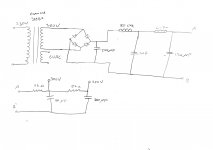
Yes, but I don't see how to. I've found a simple calculator on this website for RC and LC filtering. I can easily see the voltage drop that will happen on the filter. Lets say I'm using this power transformer. It gives 380V at 75 mA. There will be only a few voltages of drop at first LC stage with choke. Then, I should move on with RC to have a voltage drop of around 80V and another RC to have 50 more voltage drop to obtain 300V and 250V. This will give me an LCRCRC filter, am I right? B+2 will be after the first RC filter and B+1 will be the last.
After cathode bias and one stage of R-C plate filter this will be 300V on the tube.
Yes, but I don't see how to. I've found a simple calculator on this website for RC and LC filtering. I can easily see the voltage drop that will happen on the filter. Lets say I'm using this power transformer. It gives 380V at 75 mA. There will be only a few voltages of drop at first LC stage with choke. Then, I should move on with RC to have a voltage drop of around 80V and another RC to have 50 more voltage drop to obtain 300V and 250V. This will give me an LCRCRC filter, am I right? B+2 will be after the first RC filter and B+1 will be the last.
What do you mean by that?The driver power voltage is NOT critical
I have 35 (up to 70) mA at B+2 and 2-3 mA at B+1. According to these values, I've recalculated the RC values as (18k-80u-1.5k-8u). I hope I'm doing something meaningful.
Last edited:
The thing I don't understand with the psud2 is load resistance. Which resistance does it represent? Also, how am I going to specify the node currents?
Using PSUD2, I've tried building the circuit in the schematics I've posted above. However, when I put current tap and current load, the simulation goes crazy. I'm really lost at this stage. I might go for full experimental, but I don't want to really.
I might go for voltage doubler as Eli suggested, but I don't know how I can set the voltages afterwards. I've tried using PSUD2 to set the voltages with RC sections, but simulation failed.
I also don't know whether to go with bridge or voltage doubler. In case going for the voltage doubler, should I go for a lower secondary voltage transformer?
I've checked Hammond 300 series for transformer, since they have 6V filament windings too. However, I'm not sure which one to choose. Here is the model list I'm talking about.
I've got around 2 months of free time and I want to be able to start assembly in this period. That's why I'm trying to rush and give an order. Any help is more than appreciated 🙂
The thing I don't understand with the psud2 is load resistance. Which resistance does it represent? Also, how am I going to specify the node currents?
swap out the load resistance for a current tap.
@aerenyasar
As an EE, you already know the Laws of Physics don't change to accommodate your desires. A priori, a SE 6V6 must be Class "A". The plate dissipation limit for the 6V6 is 12 W. The maximum theoretical efficiency in Class "A" is 50%. You always get less, in the real world. That 5 W. number previously mentioned is absolutely correct.
I have routinely pushed the 6v6 plate dissipation just north of 18 watts. In the last few years, I've not had any failures nor plates glowing red....Further, the first input cap I use after an EZ-81 is 100uF, not 40uF as the data sheet would suggest.....Making me believe these data sheets are like the pirates codes, "their just guidelines".
A thing I notice in champs is that they do CRCRC instead of CLCRC or CLCLC, which is probably due to being guitar amp instead of hi-fi.
There's over a dozen Champs. I thought one had a choke. If not, it is because Champ was the CHEAPEST model in the line-up.
.... Lets say I'm using this power transformer. It gives 380V at 75 mA....
380V AC (and CT). The usual cap-input rectifiers will approach 530V of DC. Which is more than common electrolytic caps can stand. They expected you to use two diodes and the CT to make 266V of DC, suiting many many "250VDC" projects.
PSUD's "current taps" are imaginary concepts which are prone to have trouble at start-up. Most tube circuits take current about proportional to voltage: resistance! Not a dead-constant resistance, but far from constant current.
If you expect to deliver 300V 50mA, then figure 300V/50mA= 6k resistor loading.
If you have a 50mA load and some 2mA loads, ignore the little loads. Figure for 55mA, then later figure the droppers for the little loads.
...or simulate 30 seconds after 60 seconds from startup and ignore the warning about the current tap drawing the caps negative at startup. You want the sim to reach steady state and ignore the warm-up time.
I've tried adding 100 S of delay, but the simulation still gave weird results. So I went on with PRR's method for 35+2.55 mA. (These current values are not really correct but I wanted to test if I'm on the true path) I've selected the load resistor as 300/37.5 = 8k ohms. I've also changed the transformer to 250V @ 115 mA. The results are attached. Any feedback is appreciated.
Attachments

- Home
- Amplifiers
- Tubes / Valves
- 6V6 Single Ended Stereo Hi-Fi Advices