@Eli Duttman Thank you! That was pretty much the answer I was looking for. Now this will be a totally noob question so forgive me, but, by 5 WPC do we mean the output of 6V6 should be 5W (which I've found 2 W in previous post) or does it state the output transformer power? If it is for the 6V6, I can't see how it is possible to reach that value as I could only reach 2W. Any advice?
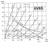
140<->410V gives a sine wave with a peak of (410-140)/2=135V and RMS is 135/√2=95,5V.Power is V²/R, (135x135)/2x8000=1,14WHere's what I've done:
1) I've decided to set my B+ as 275V. If the load was resistive, this would give 34.37 mA, lets say roughly 35 mA.
2) I've drawn a line between 275V and 35mA.
3) Without changing the gradient, I've shifted this line up to a level close to max dissipation.
4) I've seen that my grid voltage is -19V. I've checked where my line intersects 0V and 38V. For a 0<->38V input, my output is around 140<->410V
5) I've calculated the output RMS power: ((410-140)*0.707)^2 / 8000 = 4.55W.

Mona
You can easily get 5 W. from a Class "A" 6V6, when it's operating in full pentode mode. Given a small screen grid contribution to the total yield, UL mode (AKA partial triode) will produce only slightly less.
When dissipating 12 total W., a 5 W. yield is 42%. That is quite plausible. The 2 W. number is for triode mode. Triodes can't swing as close to the B+ rail as pentodes do and 20% real world efficiencies are "par for the course". Whether or not the elegant/refined sound triodes produce is worth the efficiency price is a personal matter.
When dissipating 12 total W., a 5 W. yield is 42%. That is quite plausible. The 2 W. number is for triode mode. Triodes can't swing as close to the B+ rail as pentodes do and 20% real world efficiencies are "par for the course". Whether or not the elegant/refined sound triodes produce is worth the efficiency price is a personal matter.
Yes. You were using the triode curve. As shown in RCA datasheet, 1.65W is expected max power in triode connection with 4800 ohm load.... by 5 WPC do we mean the output of 6V6 should be 5W ...
Use the 6V6 in pentode for up to 5.5W power.
Thank you again everyone. I can now see my path better. I'll go for UL mode (I really like how it sounds) so I think my 2W is ok for now. I've seen an example on internet working with 1W output power.
How can I find different curves for triode/UL/pentode modes? I can only see one curve in datasheet for 6V6.
How can I find different curves for triode/UL/pentode modes? I can only see one curve in datasheet for 6V6.
My daily driver amplifier for the last ~two years or so has been a 6SN7 push pull flea amplifier that will put out just over a watt per channel at full tilt before audible distortion. I've never heard it clip or get funky unless it was turned up too loud on purpose to far beyond comfortable listening levels. You may be fine unless your speakers are very inefficient. 🙂
Use RCA 6V6GT or GE 6V6GTA datasheet. The JJ 6V6S datasheet is incomplete.... How can I find different curves for triode/UL/pentode modes? I can only see one curve in datasheet for 6V6.
Checking the GE 6v6GTA, I've found the curves I want as you mentioned. Even though I'm not planning to build a pentode, I've tried to design one with a load-curve and now I get how it is possible to get to those power values!
One thing I've inspected is how lines change from triode to pentode. In triode, lines get steeper as screen voltage is not fixed value, but connected to plate voltage. However, in UL mode, screen will not be just connected to the plate, but there will be a "resistance" due to center tap of transformer. So, I suppose our lines in UL will be little "less steep" w.r.t. triode mode. This way, my power output in UL mode will be a bit higher than the value I've calculated in the triode curve. This seemed logical to me, since UL mode tends to have higher output power than triode in theory. Am I thinking right?
One thing I've inspected is how lines change from triode to pentode. In triode, lines get steeper as screen voltage is not fixed value, but connected to plate voltage. However, in UL mode, screen will not be just connected to the plate, but there will be a "resistance" due to center tap of transformer. So, I suppose our lines in UL will be little "less steep" w.r.t. triode mode. This way, my power output in UL mode will be a bit higher than the value I've calculated in the triode curve. This seemed logical to me, since UL mode tends to have higher output power than triode in theory. Am I thinking right?
Remember, UL is also known as partial triode. Implicit in that is also partial pentode and pentodes can swing closer to the B+ rail, which increases power O/P.
The "ultimate" UL configuration employs costly, custom, O/P transformers that contain a separate (tertiary) winding for the screen grid. The tertiary winding allows screen grid B+ to be tightly regulated at some fraction of anode B+.
Open loop linearity of full pentode mode is maximized by regulating g2 B+. In particular, highly irritating IM distortion is held down. UL mode is a form of localized NFB. Separate screen grid winding O/P "iron" combines the benefits of g2 B+ regulation with localized UL NFB.
For reasons of linearity and damping factor, full pentode mode must be combined with a substantial amount of loop NFB. Both short and global loops have been successfully employed. Numerous speakers need more damping than UL mode by itself can provide. Therefore, a small amount of loop NFB is commonplace in UL mode designs whose open loop distortion is acceptable.
Take a look at this KT88 datasheet. The KT88 is a popular high power beam tetrode and the linked datasheet shows UL curves. While much lower in power handling ability, the 6V6 is also a beam power tetrode whose general behavior will be like that of the KT88.
Although different in construction, true 3 grid power pentodes and beam power tetrodes can be electrically "equivalent". A good example is EL34 (pentode) and 6CA7 ("beamie").
Last edited:
ELi,
Thanks!
Agreed.
A Beam Power tube or Pentode tube wired in Triode Mode is a "100% Tap UL mode" (just one way to think of it).
UL mode, depending on the tube, is usually somewhere between a 20% to a 43% tap.
But some have been used at up to 75% Tap.
Beam Power mode / Pentode mode is a "0% Tap UL mode" (just one way to think of it).
And . . . a 6V6 / 6V6G / 6V6GTA is a True Beam Power tube, it has Beam Formers.
The 6V6 / 6VGT / 6V6GTA does not have a Suppressor grid (no g3).
That means it is not a True Pentode.
If you can not see the Beam Formers, one of 3 things is true:
6V6:
1. It has a Metal Housing.
6V6GT / 6V6GTA:
2. The coating on the glass prevents you from seeing the Beam Formers (or at least seeing where the metal comes through the Mica wafers, to support the Beam Formers)
3. Without Beam Formers, it is a Bogus 6V6 6V6GT / 6V6GTA (it "wants" to be a 6V6).
You can tell if a tube is a True Pentode, this way:
A True Pentode has g3, a suppressor grid. It has vertical wire supports, the 2 wires come through the mica insulator, to get support for g3.
A large majority of RF Power tubes are either, Triode, Tetrode, or Beam Power tubes.
Tetrodes have a Filament, (with or without a Cathode), Control Grid g1, Screen Grid g2, and Plate.
There are very few, if any, Audio Power Tetrode tubes.
The term "Tetrode" has been incorrectly stolen/used to describe many Audio Power tubes.
Generally for naming a tube, the filament (Direct Heated), and the Cathode if present (Indirect Heated), together are considered One Element.
Then there is the Plate (Diode) this type, and all the other types listed below have a Plate.
Then there is the Control Grid, g1 (Triode)
Then there is the Screen Grid, g2 (Tetrode)
Then there either are the Beam Formers (Beam Power); or the Suppressor Grid, g3 (Pentode)
These are historic naming conventions (and history has been revised since, I recognize that)
I first wrote about Vacuum Tubes in 1958, for an 8th grade English Term Paper (it was technically correct, but not the best english, I got a B or B-).
I do not think the English teacher checked it for facts. But I was thankful for the B or B-.
Had it been for a Science class, I would have got an A.
Such is life.
Merry Christmas! . . . Everybody
Last edited:
Eli, Summer,
Thank you! These are very important facts you're sharing. I believe these will be important for others that are reading this thread too. You explained it very clearly, I did not really know the difference between them!
And also, I hate those kind of teachers Summer :/
Merry Christmas to all! 🙂
Thank you! These are very important facts you're sharing. I believe these will be important for others that are reading this thread too. You explained it very clearly, I did not really know the difference between them!
And also, I hate those kind of teachers Summer :/
Merry Christmas to all! 🙂
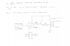
Today, I've worked on designing the output stage schematics. I've searched on internet for output transformers that I can buy. I've found GXSE10-16-8k. It's 10 Watts, much more than I need, but I wanted to choose it in case I want to change for higher powers later on (maybe on another project). Also, I couldn't find a 5W OPT according to my needs. This one is rated 8k primary on 16 ohm secondary, so I thought I can plug an 8 ohm speaker for 4k primary, which was the value I've calculated my load-line.
I'm attaching my calculations and schematics.
I'm attaching my calculations and schematics.
Attachments
With a small transformer you don't get all the power to the speaker ( more losses ) and the bass is weak ( low inductance ) . So if you can afford buy the biggest you can get 😀
While Edcor "iron" is a good value, shipping costs between New Mexico and Turkey will be very painful.
Edcor's GXSE line is good down to 40 Hz., at the rated power. In order to get reasonable performance down in the 1st octave, you need the GXSE15-5K, which can be built with the 8 Ω secondary you need.
The design should incorporate a global NFB loop, which both linearizes the "iron" at the frequency extremes and improves damping factor. The matter of phase compensation needs to be studied.
Place a 1 pole RC high pass filter whose F3 is in the 16-18 Hz. range at the amp's I/P. Suppressing infrasonic noise provides protection against O/P "iron" core saturation induced by the NFB associated LF error correction signal.
Yes Eli, that's why I've found a Edcor distributor in Spain. It is much cheaper shipping 🙂
I'm now studying on global NFB loops and phase compensation as you've said. Can you briefly elaborate the difference between a local NFB and global NFB in terms of sound quality for UL-SE? I saw some people prefer one and some prefer other. Some says you have to try it and find it yourself. What do you say?
I'm now studying on global NFB loops and phase compensation as you've said. Can you briefly elaborate the difference between a local NFB and global NFB in terms of sound quality for UL-SE? I saw some people prefer one and some prefer other. Some says you have to try it and find it yourself. What do you say?
aerenyasar,
I agree with Eli. If you can afford it, the GSXE15-5K and 8 Ohm secondary would be a good choice.
The graph you put your load lines on, looks like triode mode (from the JJ 6V6S Data Sheet).
You get lower power in Triode mode, lowest distortion at that low power, but get the highest damping factor for the 6V6 if there is no other negative feedback (Triode mode is a form of local negative feedback).
Beam Power mode has the highest power, the highest distortion, and no real damping, if there is no negative feedback.
Ultra Linear performance is between Triode mode, and Beam Power mode, if there is no other negative feedback.
GSXE15-5K- 8:
If your 8 Ohm speaker's DCR is 6 Ohms, then there are a couple of frequency ranges where the speaker's minimum impedance is 6 Ohms.
5k x (6/8) = 3750 Ohms when the speaker impedance is 6 Ohms.
The 8k / 16 Ohm Edcore:
Using the 8k primary and 16 Ohm secondary, with an 8 Ohm speaker, makes the primary look like 4k, but . . .
That will cause higher insertion loss through the transformer, due to the higher DCRs of the 8k and 16 Ohm windings.
And, 4k x (6/8) = 3k Ohms when the speaker impedance is 6 Ohms.
Decades later, I look back at my Eighth grade English teacher, Miss Moats, God rest her soul.
She would have had to go next door to the high school's Chemistry/Physics teacher. He was a Radio Amateur, and could have verified the accuracy of my vacuum tube paper (really too much work for her to do that).
When I think about it, the B or B- was fair, it was an English class, after all.
Funny how things change when you get older.
Last edited:
Yes Eli, that's why I've found a Edcor distributor in Spain. It is much cheaper shipping 🙂
I'm now studying on global NFB loops and phase compensation as you've said. Can you briefly elaborate the difference between a local NFB and global NFB in terms of sound quality for UL-SE? I saw some people prefer one and some prefer other. Some says you have to try it and find it yourself. What do you say?
As you say, pros and cons galore are present. IMO, the key in this situation is the fact that Edcor is an excellent value, but not the very best performer. Therefore, a few dB. of global NFB "kill 2 birds with 1 stone" by linearizing the "iron" and improving damping factor, which (FWIW) gets my nod.
It definitely is possible to combine the short and global NFB techniques in a single unit. Stu Hegeman's H/K Cit. 2, which is a candidate for best amp ever, contains 3 nested loops. Only a few dB. are present in the outer, global, loop. Hegeman's genius shines through in the fact that the "Deuce" is unconditionally stable.
Attachments
Eli, Summer,
Thank you for your awesome responses! I'm now working on a NFB stage but again got few questions. First, since I've not designed my input stage yet (will hopefully do that this weekend), I had to assume a gain. I've assumed 0.3 VAC input and (410-160)/2 = 125 VAC output. This results in a 416.67 V/V gain. Lets not go that far and round it to 400 V/V.
I've seen that a lot of guitar amplifier apply around 6 dB of global NFB, so I thought why not more? I've chosen to have 10 dB of NFB.
10 = 20log10(1+400*B), where B = attenuation = 0.054
For a feedback resistor Rf = 100k I've calculated Ri as:
0.0054 = Ri/(10^5*Ri) => Ri = 543 Ohms.
Is this a fine value? Is 10 dB NFB good or shall I go for higher values? I know I will have to revisit this calculations after designing the first stage, but for now I'd like to know if I'm on the path.
One other thing I couldn't figure is frequency compensation. It is possible to adjust the parallel capacitance by checking the phase response after building the amplifier, but is there a way to calculate it? I believe that calculation and real value will considerably fluctuate. I've considered designing on a SPICE, but I'm not sure if tube models are accurate enough.
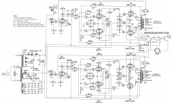
Assume a 2 VRMS signal will drive the amp into clipping. 2 VRMS is the max. O/P level out of "standard" digital signal sources. A common cathode 12AX7 section voltage gain block is all that's needed.  As the very high plate resistance 'X7 triode can run into trouble driving the Miller capacitance of a UL "final", insert a DC coupled ZVN0545A source follower between the voltage amplifier and O/P tube. The provided tweaked RCA phono preamp schematic illustrates the method.
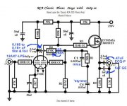
Phase compensation is a purely empirical process. The exact behavior of the O/P "iron" being used impacts greatly on what occurs. C9 and C25 are the phase compensation caps. (1/channel) in the H/K Cit. 2. Notice that only a few pF. are employed.
Connect the circuitry to a "dummy" resistive load of adequate power handling capability. Drive the amp with a 2 KHz. square wave. While examining the waveform across the "dummy" load with an o'scope, manipulate the phase compensation part's value to yield the best looking "square" wave. You will find a compromise among overshoot, ringing, and tilt that's acceptable.
As the very high plate resistance 'X7 triode can run into trouble driving the Miller capacitance of a UL "final", insert a DC coupled ZVN0545A source follower between the voltage amplifier and O/P tube. The provided tweaked RCA phono preamp schematic illustrates the method.Phase compensation is a purely empirical process. The exact behavior of the O/P "iron" being used impacts greatly on what occurs. C9 and C25 are the phase compensation caps. (1/channel) in the H/K Cit. 2. Notice that only a few pF. are employed.
Connect the circuitry to a "dummy" resistive load of adequate power handling capability. Drive the amp with a 2 KHz. square wave. While examining the waveform across the "dummy" load with an o'scope, manipulate the phase compensation part's value to yield the best looking "square" wave. You will find a compromise among overshoot, ringing, and tilt that's acceptable.
Attachments
- Home
- Amplifiers
- Tubes / Valves
- 6V6 Single Ended Stereo Hi-Fi Advices