Are the diodes correct around the 6X5? Shouldn't they be serial to the plates, to protect the rectifier, and to keep the soft start?
Are the diodes correct around the 6X5? Shouldn't they be serial to the plates, to protect the rectifier, and to keep the soft start?
No idea why that is needed at all...even for small rectifiers. Use a bigger one if worried. A pair of 6W4 will do the job; there are LOTS around, and very inexpensive.
cheers,
Douglas
OldHector, good catch!
Bandersnatch, you can read in this article why is is a good idea, especially for 5AR4 of new manufacture:
The Immortal Amplifier Mod
Bandersnatch, you can read in this article why is is a good idea, especially for 5AR4 of new manufacture:
The Immortal Amplifier Mod
OldHector, good catch!
Bandersnatch, you can read in this article why is is a good idea, especially for 5AR4 of new manufacture:
The Immortal Amplifier Mod
In that case I am now even more sure I shall not touch one of those with an Eleven Foot Bohunk( used when a Ten foot pole is not long enough ).
cheers,
Douglas
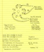
FWIW, a graphic (not original to me) shows the "correct" SS diode tweak for 5AR4s. The comparatively inexpensive Sovtek 5AR4 sounds fine and is reliable, when the tweak is employed.
My sentiments about noisy 1N4007s are well known and I suggest UF4007s, thinking less noise from the very outset must be better.
My sentiments about noisy 1N4007s are well known and I suggest UF4007s, thinking less noise from the very outset must be better.
Attachments
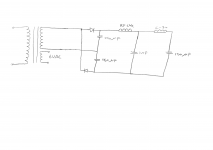
An (IMO) excellent compromise among size, weight, and cost that yields high B+ PSU performance is a well executed "full wave" voltage doubler setup. A 100 mA. supply is plenty for this project. Triad's N-68X is "perfect" for the job. 2X of this part in the doubler stack will "crush" ripple, but "hash" is present. Elephants are eaten 1 bite at a time. Follow the doubler with a LC section made from a high current RF choke and a 1000 pF. mica or C0G/NP0 ceramic cap., to suppress high order ripple overtones that could sneak into the rail via an "ordinary" filter choke's winding capacitance. Follow the "hash" filter with a LC reservoir section made from a Triad C-7X choke and a 120 μF. 'lytic.
Hi Eli! I've revisited your post and I've got a question. After the doubler stack, are you going ofr double LC section instead of LC RC? If it is double LC, what do you mean by high current RF choke, can you give an example component?
Hi Eli! I've revisited your post and I've got a question. After the doubler stack, are you going ofr double LC section instead of LC RC? If it is double LC, what do you mean by high current RF choke, can you give an example component?
After the doubler stack come 2 cascaded, not bifurcated, LC sections. The 1st is the "hash" filter and the 2nd is a "routine" reservoir setup.
This project uses a roughly 100 mA. capable B+ supply. The RF choke in the "hash" filter must comfortably tolerate that draw and yet have "substantial" inductance. Some Bourns (J.W. Miller) 8250 series parts can be suitable. Please notice the MHz. range self resonant frequencies. Part number 8250-102K-RC looks OK to me, for this project.
BTW, an added benefit of "hash" filtration is the suppression of noise that happens to be "riding" on the AC mains.
Grid to ground resistance
@aerenyasar
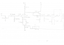
I revised the signal schematic. Neaten my poor "hen scratches".
Most of the time, exceeding 100 Kohms of grid to ground resistance with the 'X7 triode is a bad idea, lest CMiller interact and cause HF info. loss. 😡 Modern, commercial, digital signal sources must be capable of driving the 10 Kohm IHF "standard" load. Therefore, a 10 Kohm log. taper volume control is fine.
The source follower is DC coupled to the triode's plate, which makes the forward bias requisite for enhancement mode devices, like the ZVN0545A, automatic. 🙂 Size the FET's source load resistor to make ID = 2 mA. The calculation is easy, as the source follows the gate and the gate is at the same potential as the triode's anode. 😉
BTW, tube control grid and FET gate stopper resistors should be carbon composition (CC). CC resistors are both non-metallic and non-inductive. While CC parts can drift in value and be noisy, in this role those factors are unimportant. CC noise is current related and the current in these situations is vanishingly small. The exact value of a stopper resistor is very rarely critical, once it is at an appropriate level. "Taller" stoppers go hand in hand with increasing transconductance.
Hello Eli,
Sorry for my last post, I did'nt understand to post with "Quote".
I would like to ask you if for a 6SL7 the grid to ground resistance has to be around 100Kohms max like for the 12AX7?
Thanks
Alain
Sorry for my last post, I did'nt understand to post with "Quote".
I would like to ask you if for a 6SL7 the grid to ground resistance has to be around 100Kohms max like for the 12AX7?
Thanks
Alain
Hello Eli,
Sorry for my last post, I did'nt understand to post with "Quote".
I would like to ask you if for a 6SL7 the grid to ground resistance has to be around 100Kohms max like for the 12AX7?
Thanks
Alain
As the triodes in the 6SL7 and 12AX7 are closely related, sticking to 100 Kohms of total grid to ground resistance is (IMO) a good idea. Run risks only when absolutely necessary.
Are the diodes correct around the 6X5? Shouldn't they be serial to the plates, to protect the rectifier, and to keep the soft start?
No idea why that is needed at all...even for small rectifiers. Use a bigger one if worried. A pair of 6W4 will do the job; there are LOTS around, and very inexpensive.
cheers,
Douglas
The 6X5GT is here for decoration purposes. The diodes are here to simply avoid the voltage drop.
A+!
Are all the tubes run off of the same 6.3V filament winding?
If for any reason the 6X5GT filament to cathode has a short, the 'Decorative 6X5GT' will
take out all the other tubes (filament to cathode maximum voltage will have been very badly exceeded.
I never did like the idea of running the rectifier and the other tube filaments on on a single filament winding. Saves the expense of a separate 5V winding for a different rectifier.
But if the 6X5GT breaks, the expense will eliminate the savings.
Or, keep the decoration, and wire the B+ windings to a separate terminal strip, and only to the solid state diodes; not to the 6X5GT plates.
I guess I am just a "Worry Wart".
Last edited:
Are all the tubes run off of the same 6.3V filament winding?
If for any reason the 6X5GT filament to cathode has a short, the 'Decorative 6X5GT' will
take out all the other tubes (filament to cathode maximum voltage will have been very badly exceeded.
I never did like the idea of running the rectifier and the other tube filaments on on a single filament winding. Saves the expense of a separate 5V winding for a different rectifier.
But if the 6X5GT breaks, the expense will eliminate the savings.
Or, keep the decoration, and wire the B+ windings to a separate terminal strip, and only to the solid state diodes; not to the 6X5GT plates.
I guess I am just a "Worry Wart".
A+!
Hello everyone! After a few weeks of really overloaded works, I'm finally back in designing this amp!
There was a major problem in NFB loop that parafeed noticed. (signal was shorted to ground with bypass cap) I believe I've solved that problem by giving the signal from the bottom of cap and adding a DC block at the feedback.
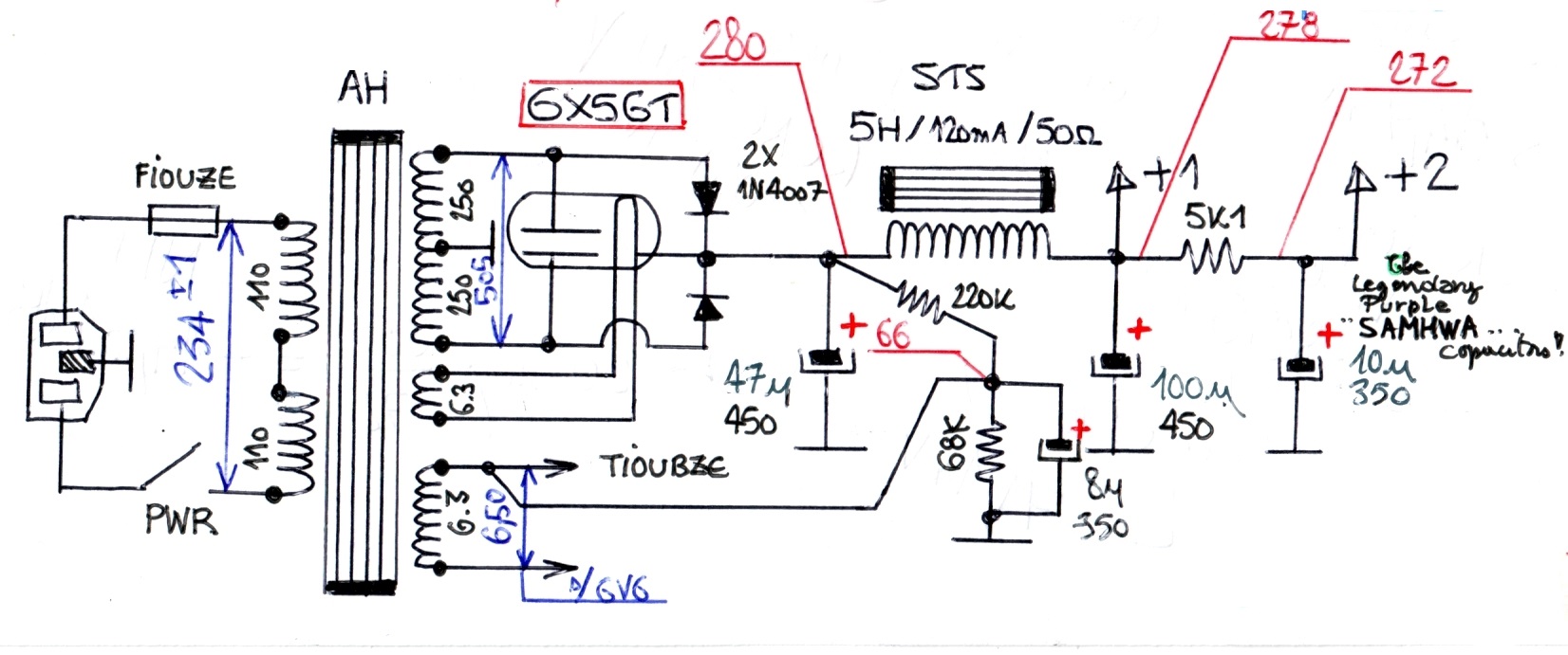
The next thing was the power supply. I've drawn it with the components advised by Eli. Thank you again for that. However, if you'd forgive my ignorance in power supplies and transformers, I've got a few questions. According to the design I've made, I need 250V B+1 and 300V B+2. How am I going to set these voltages in the current power supply? Also, I'm planning to use this transformer, as suggested by Eli.
There was a major problem in NFB loop that parafeed noticed. (signal was shorted to ground with bypass cap) I believe I've solved that problem by giving the signal from the bottom of cap and adding a DC block at the feedback.
The next thing was the power supply. I've drawn it with the components advised by Eli. Thank you again for that. However, if you'd forgive my ignorance in power supplies and transformers, I've got a few questions. According to the design I've made, I need 250V B+1 and 300V B+2. How am I going to set these voltages in the current power supply? Also, I'm planning to use this transformer, as suggested by Eli.
Attachments

The 0.22 uF capacitor in the negative feedback needs to be taken out, and replaced with a wire connection where the 0.22 uF cap was.
With the 0.22 uF cap in the negative feedback location, the feedback is reduced by 3 dB at 1,380Hz versus at 20kHz, and by 1 db at 2760Hz versus at 20kHz (there is no significant negative feedback from 20Hz to about 200Hz). Take that 0.22uF cap out.
(not the 0.22uF RC coupling caps before and after the MOSFET, leave those ones in the circuit).
You marked the grid stopper resistor on the output tube as 100k. That will roll off the high frequency.
Well, it will limit the grid current if you overdrive the grid.
But when a circuit like that has grid current, it is best to reduce the setting of the volume control . . . clipping does not sound good, a lower volume will sound better.
I would suggest that both grid stoppers value to be changed to 1k Ohms.
Just my opinions.
Last edited:
Summer thank you! The reason I've put a DC block cap was due to accurate biasing. In the case without NFB, I had a 2k cathode resistor. To make it equivalent I thought I may add a DC block and divide the resistor as 500 (R1) and 1.5k (Rk) . However, you're right.
If I remove the cap there and add a short wire, how can I obtain the bias I need? DC path will follow to the transformer over a 100k (R2) ohm resistance. Transformer will act as DC short and connect the path to 8 ohm resistance (speaker). I believe this 100k ohm and 523 ohm will not act as parallel lines. How can I set the cathode resistor as 2k in this case? Can I approximate Rk and R1 as series and ignore R2?
I'm attaching a new schematics, changing resistors to 1k as you've suggested. I've also noticed a previous ediy by Eli on MOS stage. I've also updated it. I've removed the capacitor, but right now I'm not sure if the biasing will work properly.
Attachments
Last edited:
If you started with a 2k self bias resistor before adding the negative feedback resistors,
Then use a 1.8k self bias resistor, and a 200 Ohm resistor from the bottom of the 1.8k to ground. Then adjust the 100k feedback resistor as necessary.
If the correct feedback resistors was 100k and 523 Ohms, then
The ratio of 100k to 523 Ohms = 191:1
191 x 200 Ohms = 38k for the resistor from the output transformer secondary to the 200 Ohm resistor.
Then the DCR of the output secondary is in series with 38k (adjusted feedback resistor), and that is about 38k in parallel with 200 Ohms.
38k in parallel with 200 Ohms is extremely close to 200 Ohms.
So you still have very close to 2k total resistance for the DC bias of the input tube cathode.
I hope that explains it.
Last edited:
Thank you for this clear explanation Summer! I'v updated the schematics based on your feedback. Can you give a feedback on PS design too? How can I know the secondary voltage and voltages at B+ nodes?
The transformer has a power value of 50VA. For 100mA current does it mean there will be 500V at secondary? In that case, should I adjust the capacitor values in order to match the B+ voltage levels I require?
The transformer has a power value of 50VA. For 100mA current does it mean there will be 500V at secondary? In that case, should I adjust the capacitor values in order to match the B+ voltage levels I require?
- Home
- Amplifiers
- Tubes / Valves
- 6V6 Single Ended Stereo Hi-Fi Advices