Hello Koonw,
Thanks for your replies.
I tested 4 tubes and the story is the same for all.
My kitchen lab,i use a little switching power supply :
 [/url][/IMG]
Thanks for your replies.
I tested 4 tubes and the story is the same for all.
My kitchen lab,i use a little switching power supply :
Last edited:
I Found where the mistake was:
The screen wasn't at the good potential.It was wired at the ground instead of the O v pentode.So for the pentode screen voltage wasn't 100v.
Now current value is 5ma.You showed me the way! Thanks!
The screen wasn't at the good potential.It was wired at the ground instead of the O v pentode.So for the pentode screen voltage wasn't 100v.
Now current value is 5ma.You showed me the way! Thanks!
Last edited:

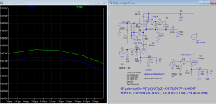
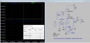
I post here my sim result for 5mA and 100V screen supply and measured effective Rp to be about 9Meg.
Attachments
Last edited:
Thanks guys!
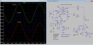
Following of 6f12p mu follower ;
Here are the results with normalized resistors values.
 [/url][/IMG]
Following of 6f12p mu follower ;
Here are the results with normalized resistors values.
An other trouble:distortion:
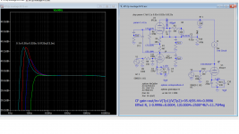
At 500hz it's ok (see picture)
At 1000hz little spikes have apared on the curve.
At 10000hz it's very ugly .
I think it's my ceramic capacitor 10nf
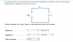
I calculated it with the effective Rcf(7,83 MΩ that i calculated and capacitor value should be 4,7nf for 4hz)
Is it wrong ?
Or should i calculate it with 470kΩ?
Both resistors are parallel...
An other question :The gain :
Input :0,1v for 1 division =0,2v
Output :10v for 1division=40v
Where is the mistake ?
 [/url][/IMG]
At 500hz it's ok (see picture)
At 1000hz little spikes have apared on the curve.
At 10000hz it's very ugly .
I think it's my ceramic capacitor 10nf
I calculated it with the effective Rcf(7,83 MΩ that i calculated and capacitor value should be 4,7nf for 4hz)
Is it wrong ?
Or should i calculate it with 470kΩ?
Both resistors are parallel...
An other question :The gain :
Input :0,1v for 1 division =0,2v
Output :10v for 1division=40v
Where is the mistake ?
Last edited:
It appears that you are connecting the signals directly to the scope's channel inputs.
1. If your generator has a 50 Ohm output, terminate it with 50 Ohms (A 47 Ohm resistor will get you close).
If your generator has a 600 Ohm output, terminate it with 600 Ohms (A 620 Ohm resistor will get you close).
Without any termination, you are driving the generator into 470K Ohms, essentially no load, the generator output will be 2X the generator's voltage setting.
2. Make sure the scope channels 1 and 2, are both set to Probe = 1X
Last edited:
I think the screen resistor is too low as it draws too much current that causes the distortion, use Rs of 10K is better. Or increase the bias of top pentode should help.
Attachments
Last edited:
The coupling capacitor in upper tube should be reduced as you already pointed out as effective Rp is greater now. Still think you need to bypass the screen to cathode with a capacitor.
Last edited:
Hello, thanks for your replies.
The trouble comes from my 10€ functions generator,��
But there is something to write about this capacitor.
How should it be calculate ?
Only with the effective load ?
 [/url][/IMG]
The trouble comes from my 10€ functions generator,��
But there is something to write about this capacitor.
How should it be calculate ?
Only with the effective load ?
Attachments
RC constant for Tp1/Tp2 (0.0001µ/1000Meg) has very little loading on signal and frequency response down to 10Hz, is ideal for measuring the tinny difference of gyrator. But there is no coupling capacitor here. The gyrator has 164M effective Rp, more than 10 times the pentode for bottom triode.
Attachments
Last edited:
Hello , thanks for this post.
The interest of using the mu follower with 6f12p is there is a pentode and a triode in the same tube with very good characteristics.
I have a project with gyrator builded with an irf710 MOSFET and a DHT tube.
I want to learn LT Spice. I eard that there is a freeware version,right? Where should i start? Please.
Last edited:
RC constant for Tp1/Tp2 (0.0001µ/1000Meg) has very little loading on signal and frequency response down to 10Hz, is ideal for measuring the tinny difference of gyrator. But there is no coupling capacitor here. The gyrator has 164M effective Rp, more than 10 times the pentode for bottom triode.
Correction: Load should taken out on source top of 300 Ohms. Effective remeasured Rp is (?), sorry about that.
Last edited:
- Home
- Amplifiers
- Tubes / Valves
- Mu stage driver