Hi Mr. Miles!
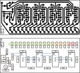
I dont understand, this layout you gave has also diodes in between collector and emitter. Should it be between collector and output or may leave like that?
Regards, Toivo.
I dont understand, this layout you gave has also diodes in between collector and emitter. Should it be between collector and output or may leave like that?
Regards, Toivo.
Hi Mr. Miles!
I dont understand, this layout you gave has also diodes in between collector and emitter. Should it be between collector and output or may leave like that?
Regards, Toivo.
It is irelevant,
Regsrds
Ok, thanks for Your patience Mr. Mile!
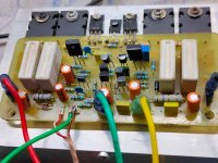
I’ll assamble the boards and let you know how it sounds!
Thanks for sharing!
Regards, Toivo
I’ll assamble the boards and let you know how it sounds!
Thanks for sharing!
Regards, Toivo
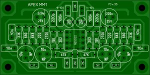
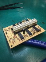
APEX VU12S PCB size 82,5x65mm.
Hi,
the circuit diagram can also be posted.
thanks.
Maybe try to use AX-14P
Hi.
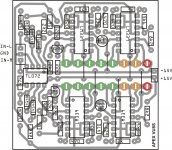
Did you set up this circuit?
I have dc voltage at the output of the same map and pcb.
Hi Prazi, thanks for your words, even so you are a spark pcb design 🙂. Have a nice new year.
Regards
Regards


- Home
- Amplifiers
- Solid State
- 100W Ultimate Fidelity Amplifier