Hi M. Mile, I think you should put more transistors, because is always a chalenge to put them in PCB 🙂
Attachments

Hi M. Mile, I think you should put more transistors, because is always a chalenge to put them in PCB
If the PCB is going to be distributed by pdf image and then etched and drilled manually (as opposed to sharing gerbers), does it make any sense to use SOT-23 and SOD-123? That way you can put in more transistors 😛 and also you don't need to drill two hundred holes per channel by hand 🙁
Hi, I need a speaker protect circuit for ax14 but running at 25V DC per rail. Been so long since I've started my AX14 circuits with ML3 preamps. My SR200 is still playing really well.
Any help will be appreciated.
Any help will be appreciated.
Hi, I need a speaker protect circuit for ax14 but running at 25V DC per rail. Been so long since I've started my AX14 circuits with ML3 preamps. My SR200 is still playing really well.
Any help will be appreciated.
Attachments

Some questions
hi everyone, i'm completing my AX-14 with Mr. Prashant Pawar (Prasi) pcb and I have a couple of beginner questions.
The first is about how to measure the bias, it is correct to say that I have to measure the voltage between the two emitter of the transistor Q12 and Q14 and divide the value by 0.66, which is the value of the two resistors in series R25 and R27 from 0.33. This value must be around 40V if I want to get 60mA.
Also, in case of hum, if I put a jumper in the R23 position, is correct to consider C13 useless?
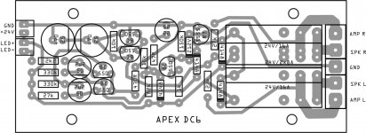
The other question is about the Speaker protection, I have seen the diagram of the DC6, but I would need it for a 35v power supply. I tried to understand the differences between the schemes of post n. 13346 and n. 11502 and for led resistance the value should be 3.1 k but i don't know which zener to use. The capacitors I think they will all have to be 50v, but I have no idea what other modifications in the components I will have to use. Last question is about Q1 and Q2: whats happens if they are not matched?
Thank you in advance for all the help you will give me,
best regards
Sergio
hi everyone, i'm completing my AX-14 with Mr. Prashant Pawar (Prasi) pcb and I have a couple of beginner questions.
The first is about how to measure the bias, it is correct to say that I have to measure the voltage between the two emitter of the transistor Q12 and Q14 and divide the value by 0.66, which is the value of the two resistors in series R25 and R27 from 0.33. This value must be around 40V if I want to get 60mA.
Also, in case of hum, if I put a jumper in the R23 position, is correct to consider C13 useless?
The other question is about the Speaker protection, I have seen the diagram of the DC6, but I would need it for a 35v power supply. I tried to understand the differences between the schemes of post n. 13346 and n. 11502 and for led resistance the value should be 3.1 k but i don't know which zener to use. The capacitors I think they will all have to be 50v, but I have no idea what other modifications in the components I will have to use. Last question is about Q1 and Q2: whats happens if they are not matched?
Thank you in advance for all the help you will give me,
best regards
Sergio
Hi Sergio,
Pl read up on below post and then post any questions that you may have.
100W Ultimate Fidelity Amplifier
yes, you may disregard C13 and instead put the resistor.
if q1 q2 are not matched, you may get higher offest voltage between speaker out and gnd.
Pl read up on below post and then post any questions that you may have.
100W Ultimate Fidelity Amplifier
yes, you may disregard C13 and instead put the resistor.
if q1 q2 are not matched, you may get higher offest voltage between speaker out and gnd.
Hi, Mr. Mile!
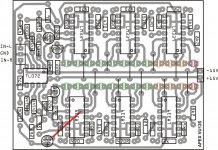
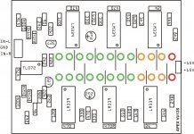
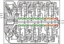
AX14 diodes D5 and D4 seems to connected wrong on the pcb. D4 is connected directly 2sa1943 C and E. Same with the D5. Or I messing up something?
Regards, Toivo.
AX14 diodes D5 and D4 seems to connected wrong on the pcb. D4 is connected directly 2sa1943 C and E. Same with the D5. Or I messing up something?
Regards, Toivo.
Hi, Mr. Mile!
AX14 diodes D5 and D4 seems to connected wrong on the pcb. D4 is connected directly 2sa1943 C and E. Same with the D5. Or I messing up something?
Regards, Toivo.
Maybe easier if you can post both the schematics and the pcb layout that you are considering.
Regards.
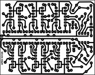
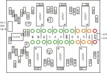
If you look the component layout and pcb drawing page 16 post#156 D4 and D5 placeing on the outlut transitors collector and emitter.
Hi!
There’s written about wrong polarity, but diodes are connected wrong according to schematic. One end of diode must go to output and other to voltages rail.
Regards, Toivo
There’s written about wrong polarity, but diodes are connected wrong according to schematic. One end of diode must go to output and other to voltages rail.
Regards, Toivo
Hi, Mr. Mile!
AX14 diodes D5 and D4 seems to connected wrong on the pcb. D4 is connected directly 2sa1943 C and E. Same with the D5. Or I messing up something?
Regards, Toivo.
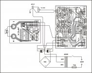
Use this circuit.
Attachments
- Home
- Amplifiers
- Solid State
- 100W Ultimate Fidelity Amplifier