Solder Problems
Hate to be terse but the soldering is terrible. Most of the joints are cold could be poor quality solder, low quality solder iron and soldering technique or all three.
Some of the joints have what appears to be corrosion on and around them and some have very little solder on them at all.
There are lots of videos on youtube on this subject. Money spent on quality tools is always money well spent. Good quality solder is a must have. A couple hours practice after getting the proper equipment will sure make your DIY project less problematic.
Just friendly advice from an old guy😀
A321Drvr,
I'm reading this thread because I suspect there may be a Wayne's BA 2018 under the Christmas tree and I happened to read your post.
My soldering iron sucks. I can't believe I have managed with it thus far. If I posted a photo, it would give you (and countless others) nightmares. Actually, all my projects still work which feels like a miracle.
So what do you recommend?
Hakko soldering irons - Nelson Pass uses them, depends on what you want to pay. I have the FX-888D (2 actually).
Hate to be terse but the soldering is terrible.
Just friendly advice from an old guy😀
No problem. I asked for advice. And you are no doubt correct.
I have a battleship old Weller that I love, but used a friend’s temp-control Hakko for a few months and can wholeheartedly recommend!!
Also, the Fire-Metall solder will be in stock again soon, and it is unquestionably the best solder I’ve ever used.
Also, the Fire-Metall solder will be in stock again soon, and it is unquestionably the best solder I’ve ever used.
I have a KSGER T12 temperature controlled soldering station, and a TS80 9v 18w soldering iron, plus a bottle of MG Chemicals Flux Colophane. The problem is most likely lack of practice.I have a battleship old Weller that I love, but used a friend’s temp-control Hakko for a few months and can wholeheartedly recommend!!
Also, the Fire-Metall solder will be in stock again soon, and it is unquestionably the best solder I’ve ever used.
Though my ACA 1.6 and Korg B1 work, as well as a microphone preamp I built with a LM381N 45 years or so ago. But between that ancient project and very recently, I played with software, not electronics. It still seems that one should be able to trouble shoot a non working circuit.
Thanks guys.
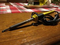
The tip on mine is about half as long as it was new. I guess the acid in the rosin has dissolved the rest? Actually, there is no tip. It's just a ragged lump of ???
Somehow I manage to make it work, but I am going to get myself something good. Life is too short to use that darned thing anymore.
The tip on mine is about half as long as it was new. I guess the acid in the rosin has dissolved the rest? Actually, there is no tip. It's just a ragged lump of ???
Somehow I manage to make it work, but I am going to get myself something good. Life is too short to use that darned thing anymore.
Hopefully wear and tear ate your tip - don't use acid core solder on electronics.
I also use the Hakko 888 after a Radio Shack 30 watt for years, the Hakko is a nice piece of kit. And buy from a reputable dealer - there are knock offs out there that are, well, not worth a crap.
I also use the Hakko 888 after a Radio Shack 30 watt for years, the Hakko is a nice piece of kit. And buy from a reputable dealer - there are knock offs out there that are, well, not worth a crap.
Good advice, buy genuine from an authorized distributor locally. Don't buy on ebay from any site in China.
All the stuff I use says "rosin core" but who knows. I have done quite a lot of soldering with it, but I've never had the sponge thing to wipe it off so maybe just wear and tear?
When I get the new one, I am going to learn how to use and treat it right. The one I have has been "abused" I am sure.
When I get the new one, I am going to learn how to use and treat it right. The one I have has been "abused" I am sure.
What about Amazon?
Looking at the Hakko 888 now. Compared to the one I have been using it seems like I would be upgrading from a rusted out 1978 Honda Civic to a Porsche 911.
Looking at the Hakko 888 now. Compared to the one I have been using it seems like I would be upgrading from a rusted out 1978 Honda Civic to a Porsche 911.
What about Amazon?
Looking at the Hakko 888 now. Compared to the one I have been using it seems like I would be upgrading from a rusted out 1978 Honda Civic to a Porsche 911.
The Hakko is a dream to use. Try to look for one bundled with a bunch of free tips, thats how I found mine.
Love my old Weller garage station but got a Hakko for the upstairs
https://www.tequipment.net/hakko/soldering-equipment-1/soldering-stations/
https://www.tequipment.net/hakko/soldering-equipment-1/soldering-stations/

My Hakko FX888 is circa 2012, before it changed to the digital display. It has an analog dial for temp setting. Still working great after all these years.
I would also recommend The Yihua 862 BD with SMD. Hot air is convenient for heating heatshrink tubing as well. No need to bust out my heat gun anymore especially when making interconnects.
https://www.amazon.com/gp/product/B07RY5XWVG/ref=ppx_yo_dt_b_search_asin_title?ie=UTF8&psc=1

I built up a pair of the original purple boards and listened happily for a few months. Then one board stopped working. Since I had slightly butchered it by lifting some traces while trying to R&R a transistor I had installed backwards, I decided to build up another board, as I had extra PCBs and parts.
The second board never worked. I've inspected everything over and over, and have looked for mistakes, but I can't see anything. The board that works draws 30mA per rail, it is easy to balance the DC out, and the LED is brightly lit. On the board that doesn't work, the rails draw 18mA each, the DC offset never gets below 6v and the LED is dimly lit. I figured with one working board, I should be able to figure out what was wrong with the other board, but that has not proven to be the case.
I could build up another board, but at this point I think I'd rather learn something. So I am asking for some troubleshooting help. What should I measure to find the problem, and why?
I have included four images. Two show the front and back of the non-working board. and the other two show DC voltage measurements of the good and bad boards.
Any help appreciated. Thank you.
I was very gratified to read your post as I had been having similar problems and thought it was just me.
potted history....I built up two sets of the store boards to make a balanced pre...they worked Ok but I suspected that one board had minor hum problems that manifest themselves with power supplies using on-board transformers ( VRDN or Millet ) so I built up another board. On that one one channel could be offset zeroed, the other one just floated around. Checked the parts and the soldering with no clues.....my soldering skills are improving, my trouble shooting skills are non existent. So being either stubborn or unwilling to admit defeat I built up two more sets with similar results...one channel OK the other wobbly ( not always the same one ) Whilst doing this I had found a magnifier light, Cardas solder, fibreglass cleaning brush, reduced the temp of the iron and watched many you-tube soldering videos which emphasised how easy it was to solder SMD parts. The weird thing about the BA18 board is the fiddly bits ( SMD soldering ) come first but its only after you stuff all the other components that you find out if it works or not.
Eventually I concluded it must be the Jfets as all the other stuffing and soldering is straightforward so I desoldered the Jfets on the faulty channels and soldered in new ones. This is even harder to do on a populated board than on a fresh one. This saved two of the boards that now work fine. One of the things I bought in the previous phase was an SMD practice board kit...$9 on Amazon, which gives you a selection of test components to assemble and was the best $9 I ever spent. That plus thin solder, cleaning the board and using lots of flux seemed to do the trick. I am shortsighted and transition lenses and magnifying glasses dont work well together, so most of my detailed soldering work is done glasses free ( using clear goggles of course ) and very close. I will try soon to confirm this new found skill by building another board but my experience might help
I did suggest to 6L6 that the store sell SMD populated boards for the ham-fisted among us but he very rightly made the point that current practice with electronics is SMD so we are well advised to get used to it. If there was a test process to apply to the Jfets fitted to a fresh board that would be useful. I have found this project to be a significant learning process....and it is a great pre amp, so thanks Wayne for the design and 6L6 for the support
+1 on any SMD practice kit, thin solder, and magnification.
Additions / other tips I've picked up:
If you have an iron where you can swap tips, use the smallest reasonable tip. I use a conical tip, but a small chisel will do. Swiping a hot solder blob across the pad and the leg may look good at first glance. Heat the pad and the leg simultaneously to help ensure a good joint.
I differ a bit re: lowering the temp, but that depends on what temp and what tip you were using just prior and if your iron will adjust output to keep a steady temp. If you have the temp running higher than normal to solder heatsinks to ground planes using a tip with a small mass, then definitely lower it. Otherwise, just leave your temp set per the solder you're using, use the right tip, and let the iron do the work. I rarely adjust my temp. If the iron has a fixed temp and/or you only have one tip, do the best you can with fine solder.
Do whatever you can to steady your iron hand, particularly if you have a longer distance between your hand and the tip. Try writing w/o resting your hand. Shorter irons/tips to get closer to the work are a dream. With the hand feeding the solder, get your fingers right down close, so you can hit the joint accurately and quickly.
Get in and out. It should not take hardly any time at all to solder those teeny legs to those pads. A one-one-thousand count is more than enough, and a little dab 'll do ya. Wetting those pads and legs takes just a wee bit of solder.
Examine and clean every joint under high magnification before moving on to the next part. Don't wait to examine until after you've built the full boards. Beep test / resistance check as appropriate to check your work. Bad joints and lifting pads seems to be more common than burning up parts with a lingering or misplaced iron. If you don't have good magnification, use your phone.
re: glasses and magnification.
I don't want to turn this thread into tips for soldering SMD and soldering hacks for people with less-than-perfect vision. It took me a while to get comfortable, so I thought I'd share my experience. The right gear helped a ton, and practicing helped even more. It's a breeze now. I may like it even more than through hole. Naaaaaaaah!
As always, YMMV.
Additions / other tips I've picked up:
If you have an iron where you can swap tips, use the smallest reasonable tip. I use a conical tip, but a small chisel will do. Swiping a hot solder blob across the pad and the leg may look good at first glance. Heat the pad and the leg simultaneously to help ensure a good joint.
I differ a bit re: lowering the temp, but that depends on what temp and what tip you were using just prior and if your iron will adjust output to keep a steady temp. If you have the temp running higher than normal to solder heatsinks to ground planes using a tip with a small mass, then definitely lower it. Otherwise, just leave your temp set per the solder you're using, use the right tip, and let the iron do the work. I rarely adjust my temp. If the iron has a fixed temp and/or you only have one tip, do the best you can with fine solder.
Do whatever you can to steady your iron hand, particularly if you have a longer distance between your hand and the tip. Try writing w/o resting your hand. Shorter irons/tips to get closer to the work are a dream. With the hand feeding the solder, get your fingers right down close, so you can hit the joint accurately and quickly.
Get in and out. It should not take hardly any time at all to solder those teeny legs to those pads. A one-one-thousand count is more than enough, and a little dab 'll do ya. Wetting those pads and legs takes just a wee bit of solder.
Examine and clean every joint under high magnification before moving on to the next part. Don't wait to examine until after you've built the full boards. Beep test / resistance check as appropriate to check your work. Bad joints and lifting pads seems to be more common than burning up parts with a lingering or misplaced iron. If you don't have good magnification, use your phone.
re: glasses and magnification.
I'm in the same boat as phomchick. I have lousy results with prescription lenses under most magnifiers. Below is what I use. Since these sit away from my eyes, I can get away with my prescription lenses under them. Other things like wearing dime store readers over my prescription just don't work. That's just my situation though.
https://www.amazon.com/gp/product/B0015IN8J6/ref=ppx_yo_dt_b_asin_title_o09_s01?ie=UTF8&psc=1
You can get kits with multiple lenses or just the ones you want at different focal lengths / magnification.
https://www.amazon.com/gp/product/B0015IN8HS/ref=ppx_yo_dt_b_asin_title_o08_s00?ie=UTF8&psc=1
To inspect, I swing the loupe around.
https://www.amazon.com/gp/product/B0015ILDZW/ref=ppx_yo_dt_b_asin_title_o01_s00?ie=UTF8&psc=1
If you're not doing a lot of SMD work, that's probably too much to invest. However, it also helps me with tightly populated through hole boards, and it's much cheaper than a proper microscope. Did I mention my vision is pretty bad... 🙂
I've even considered products like this, but I can't get past the cost.
Magnifying Eyeglasses with Light | Customized With Your Rx
I've even considered getting a pair of el-cheapo "Coke bottles" made. 3.5x or 5x at about an 8" focal length would work well for me. Think reading glasses, but at a shorter focal length and with more magnification. My Costco usually runs vision deals a few times a year for "$99 a pair". Other stores may also.
I don't want to turn this thread into tips for soldering SMD and soldering hacks for people with less-than-perfect vision. It took me a while to get comfortable, so I thought I'd share my experience. The right gear helped a ton, and practicing helped even more. It's a breeze now. I may like it even more than through hole. Naaaaaaaah!
As always, YMMV.
Post #263 Wayne is talking about the original single-channel purple PCBs, not the Stereo.
But I still think you have to change R20 to 10K and R18 to 27K for use with balanced input. You can't have 100R on IN+ and 10K on IN-
I'm in the middle of building a balanced version, I used all the values from the schematic with no changes.
When I first tried wiring the inputs with the ground jumped to IN - or IN +, I had very low gain.
With the inputs wired without using the ground pin on the PC board, gain improved, with a slight hum. Still not happy with the sound and gain.
Not sure if the hum is related, I was going to work on that tomorrow.
- Home
- Amplifiers
- Pass Labs
- Wayne's BA 2018 linestage