Having just read the other forum thread, it seems 'measurements' are just by ear so far. The topic seems to be the ARC SP8 preamp, but listening seems to include an unknown main amp and speakers, so it's not clear if the SP8 is connected to a power amp and speakers, or ...?
The fault-finding I could make out so far was:
- no preamp ... virtually no hum in the power amp (valve 211)
- hum irrespective of input and with zero gain still hear it as you switch mute on/off
- can hear it a lot more at full gain
No idea what the reference to valve 211 is about?
The second description is ambiguous as it may be saying there is hum from the main amp and interconnect when the mute switch is on - or it may not ....
The third description is also ambiguous as it doesn't identify what the various inputs are doing (shorted, open, selected ...) and if there is a relative difference (eg. they are all the same except the phono channel).
Do you have double ground termination of RCA connector between pre-amp and output amp and may be between CD player and pre-amp?
It takes someone long time to solve this, maybe this helpful:
6dj8 phono pre to 12au7 pre hum
humm and buzz
Refer to this article:https://www.diyaudio.com/forums/att...m-buzz-groundingproblemsrev1p4danieljoffe-pdf
It takes someone long time to solve this, maybe this helpful:
6dj8 phono pre to 12au7 pre hum
humm and buzz
Refer to this article:https://www.diyaudio.com/forums/att...m-buzz-groundingproblemsrev1p4danieljoffe-pdf
Last edited:
Was this amp working at some point and now it isn't? If so, shielding the transformer won't do much good.
Tom
Tom
So I have had a replacement mains transformer fitted.....so this could be creating a larger than desirable field. This would explain all the benefit of shielding I have had. What is the best way to shield the transformer effectively. Steel / Copper ?
Mu Metal is probably the best but you might struggle getting hold of it. It is super effective... but only if that is your problem to begin with.
Mu-metal - Wikipedia
Begin with the basics as I mentioned.
If you suspect a transformer then as a test remove it physically and connect it via long leads and see if the problem is removed.
OMG!!!! finally a hum free pre-amp......
So I tried all the inputs with a shorting plug, and sadly no change or difference, that is until I put in the shorting plugs into the tape output, and effectively created a 20 db attenuator.....gave me a fleeting hope, but not the answer.
So you begin with just the preamp and its power amp connected up and a pair of speakers. Fit shorting plugs to the inputs under test (go through them all) and see if there is any background hum and whether or not the volume affects it. Have nothing else connected to the preamp.
Inputs that float can be noisy, hence the shorting plugs.
50 Hz hum sounds like either a ground loop or a radiated field (such as from a transformer) being picked up.
The power supply with its full wave rectifiers would produce 100Hz rather than 50Hz if for example the noise was caused by ripple on the rails.
So I tried all the inputs with a shorting plug, and sadly no change or difference, that is until I put in the shorting plugs into the tape output, and effectively created a 20 db attenuator.....gave me a fleeting hope, but not the answer.
sorry for the title...this was written before I realised what the short created in effect the attenuator!!
So still humming...
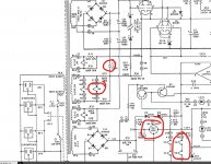
Lets work back forward by starting at the RCA outputs. See diagram.
1/ Does it hum with the mute switch on? This is shown as shorting the output to ground. If it does still hum then there must be a ground loop somewhere.
2/ If it doesn't hum in mute then switch the mute off. Now short out R24 on both channels. Does it still hum or not?
3/ If it is still OK in 2 above then remove the short across R24 and now short R20 in both channels. Does it still hum or not?
You have to be creative in trying to pin something like this down.
Any chance the hum could be from the AC supplied heaters?
Attachments

Electric coupling: any grounded plate that conducts reasonably well can shield electric fields, so any kind of metal foil can do the trick, provided you can reliably ground it. Copper foil and steel will work well, aluminium may be problematic because of the need to ground it reliably.
Magnetic coupling: low-frequency magnetic fields can only be shielded by a shield with a high permeability or a thickness several times greater than the skin depth, which decreases with increasing permeability (see Skin effect - Wikipedia ). For 50 Hz, that means a copper layer of several centimetres thick or a steel layer of several millimetres thick. Mu-metal is an alloy meant specifically for low-frequency magnetic shielding, see Mu-metal - Wikipedia
I think it is best to first see what comes out of Mooly's shorting plug experiment.
The absorbing magnetic material is not that critical. I noticed magnetic coupling between an OPT & OP too close together & incorrectly oriented.
An ordinary steel chassis bottom stuffed between them caused a drop of about 20 db in the magnetic coulping.🙂
So still humming...
Lets work back forward by starting at the RCA outputs. See diagram.
1/ Does it hum with the mute switch on? This is shown as shorting the output to ground. If it does still hum then there must be a ground loop somewhere.
No
2/ If it doesn't hum in mute then switch the mute off. Now short out R24 on both channels. Does it still hum or not?
It hums a lot more,
I left 2 wire connections onto the location in the diagram of R72 and C42/C9 ready to take to a nearby earth, they were already joined together LH/RH channels and it was already hummy and microphonic.
Connecting these connections to earth created a large buzz, I also tried this with the connection in place to the earth and taking it off mute - again very loud buzz/hum.
3/ If it is still OK in 2 above then remove the short across R24 and now short R20 in both channels. Does it still hum or not?
You have to be creative in trying to pin something like this down.
Any chance the hum could be from the AC supplied heaters?
I wouldn't have expected hum in that second step. The DC conditions should be preserved however the AC feedback loop would be broken and the gain very high on that stage... might be worth looking further into that for clues.
I would say it shouldn't hum in that state. If the rails are clean then where is it coming from? Heaters maybe? Or are we looking at possible limitations of the design itself?
Maybe some of the others have some ideas on that.
With clean rails and no stray pickup or heater issues it should be silent. Amplifiers don't hum by themselves.
Just having a look with you mentioning that...
it looks like V6 is pure AC but floated at 160 volts DC with 1uF tying it to the centre tap of the high voltage winding edit... nope there is a faint blob on the circuit tying it to ground via the cap, not the centre tap. V4 and V5 are fed from a 7824 regulator so should be clean.
it looks like V6 is pure AC but floated at 160 volts DC with 1uF tying it to the centre tap of the high voltage winding edit... nope there is a faint blob on the circuit tying it to ground via the cap, not the centre tap. V4 and V5 are fed from a 7824 regulator so should be clean.
Attachments
Ground one side of the heaters and see what happens.
So is this the DC heater side feeding V4 and V5?
How do I do this, sorry for numpty question.....
Attachments
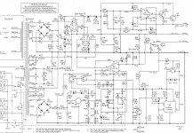
Just having a look with you mentioning that...
it looks like V6 is pure AC but floated at 160 volts DC with 1uF tying it to the centre tap of the high voltage winding edit... nope there is a faint blob on the circuit tying it to ground via the cap, not the centre tap. V4 and V5 are fed from a 7824 regulator so should be clean.
Just a thought, this circuit is from an earlier version of the SP8, mine is later. But I've noticed that the original had a cap C35 in your image across the 24V regulator, mine which is Rev. E does not have one - could this help?
I did actually change C16 as my repair guy had put in a dangly version solder glued to the location as instead of axial he had the 2 ends push through type. I hoped this would make a difference....but not to hum, strangely and probably incorrectly I assume it possibly sounded a bit cleaner, but who knows
You would need to study the circuit regarding the cap. To remove it from the circuit I posted would not be advisable because the regulator is fed via that 10 ohm and that means the impedance at the input to the reg would be very high... not good.
I could understand the cap being removed if the 10 ohm was also shorted out and perhaps also a larger value then fitted for C12.
From what you say about the 'dangly cap' it sounds like the unit has a bit of previous history and so could it possible anything else has been altered or changed?
That could be a valid mod if issues were found with ripple occurring because of the regulator dropping out of regulation under slightly low mains voltage conditions.
- Home
- Amplifiers
- Tubes / Valves
- cheap oscilloscope? to help find my damn hummmmm