Regarding post #138: Probably both. A capacitor can block the DC voltage without much attenuation of the hum when the time constant with the audio interface's input resistance is large enough, but you can still get rather nasty charging current spikes when you connect the probe. So I'd use a resistor large enough to keep the current below 10 mA at all times and a coupling capacitor. IC inputs are usually latch-up tested with 100 mA current peaks, so 10 mA should be safe, or so I hope.
Assuming the high voltage comes up slowly, you can then still reduce the stress on the audio interface and reduce the risk of electrocuting yourself by connecting the probe before turning on the amplifier.
Assuming the high voltage comes up slowly, you can then still reduce the stress on the audio interface and reduce the risk of electrocuting yourself by connecting the probe before turning on the amplifier.
If I just stick to the input grid of each valve after the coupling cap then that should be low DC voltage? (maximum signal voltage is 2V p2p I think) and there should not be any DC there I guess.
If it is valve gear then the resistive and capacitive loading of the do-dah might be to much... to low an impedance. A proper scope used with a normal divider probe has a 10 meg ohm input impedance.
It all depends on the input impedance and input sensitivity of the do-dah you feed the signal into meaning you will have to scale parts to suit.
Use a DC blocking cap such as a film cap of 400v rating. Series resistor of wattage to withstand the expected full voltage encountered. Use back to back Zener and diode network directly across the input of the do-dah as voltage clamp to prevent excess voltage making its way in. I would guess something like protection clamping at -/+5 volts would be OK.
Its not a great way of doing things tbh... proper scope is infinitely better 🙂
The do-dah is
Input impedance approx. 27 kΩ
Max. input level 2 dBV
So for a signal level on the input grid of each valve I suppose that will be safe/ok?
This will be compared to the input impedance of a 12AX7 and a 6DJ8 I suppose?
27k is really low. What it means is that it might kill the signal on the valve grid depending what is feeding that grid. For example if the previous stage is taken from an anode with 100k anode resistor feed then the 27k will load it to much. It wont harm anything but it will distort and reduce the signal.
Levels are OK, it is surges you have to be careful of, even if the signal to the do-dah is AC coupled. If you are certain that there is no high voltage at the point you are measuring to then it should be OK but there is always a real risk of something happening.
Levels are OK, it is surges you have to be careful of, even if the signal to the do-dah is AC coupled. If you are certain that there is no high voltage at the point you are measuring to then it should be OK but there is always a real risk of something happening.
And just to add... if the interstage coupling to the grid is via a small cap then the 27k will alter the response of the circuit and the low frequencies will be attenuated severely.
It all depends on the input impedance and input sensitivity of the do-dah you feed the signal into meaning you will have to scale parts to suit.
Use a DC blocking cap such as a film cap of 400v rating. Series resistor of wattage to withstand the expected full voltage encountered. Use back to back Zener and diode network directly across the input of the do-dah as voltage clamp to prevent excess voltage making its way in. I would guess something like protection clamping at -/+5 volts would be OK.
Its not a great way of doing things tbh... proper scope is infinitely better 🙂
ok - will leave alone....
should I consider maybe something like this to do it properly?
https://cpc.farnell.com/multicomp-pro/mp720010-eu-uk/digital-storage-oscilloscope-50mhz/dp/IN08385
just prefer to not spend a lot on something I may not use much!
If you want to use the audio interface, you could either try to correct for the loading effects (for example, when you know by inspection of the circuit that the 27 kohm will reduce the hum level by a factor of four, multiply what you measure by four), or make some buffer to drive the audio interface, or put a big resistor in series and accept the signal loss and noise you get from that. The last method only works if the hum is then still big enough to be measurable above the noise. Can you also do narrow-bamd measurements like spectrum analyses?
ok - will leave alone....
should I consider maybe something like this to do it properly?
https://cpc.farnell.com/multicomp-pro/mp720010-eu-uk/digital-storage-oscilloscope-50mhz/dp/IN08385
just prefer to not spend a lot on something I may not use much!
It is a 'proper' scope although it has limitations on resolution at high frequencies but it would cover all audio work that you would do.
Its a tough call if you say you may not use it much because although the scope is the single most useful bit of kit you can have it still doesn't guarantee you will find a solution to your problem. It is a diagnostic tool but you still have to act on the information it provides.
hey what about just using a passive high impedance probe into the audio interface, that would give a level of protection wouldn't it?
Yes, but it would also reduce the signal level proportionately. 27k input impedance and say a 1meg probe would mean you see only 26 millivolts for every volt applied.
Audio amps are not forgiving of grounding sins, so an unbalanced scope input is a recipe for trouble. You could possible ground the scope to the signal generator and amp input, but you can not safely connect the scope probe ground to the speaker return. When I did professional audio, I built a test speaker with protection, ie capacitor, resistor pad and Zenner clamps. Your ears have almost 100 dB dynamic range so you can hear a small hum that will be a ~flat line on a scope unless you crank up the input sensitivity. 90% of hum problems are grounding mistakes.
A typical 1 megohm 1:1 oscilloscope probe is only 1 megohm when loaded with a 1 megohm oscilloscope input; essentially it is just a funny cable. A 10:1 probe has a 9 megohm series resistor built in, but then there is almost no signal left with a 27 kohm load.
A typical 1 megohm 1:1 oscilloscope probe is only 1 megohm when loaded with a 1 megohm oscilloscope input; essentially it is just a funny cable. A 10:1 probe has a 9 megohm series resistor built in, but then there is almost no signal left with a 27 kohm load.
Of course 🙂 I don't know what I was thinking there.
Audio amps are not forgiving of grounding sins, so an unbalanced scope input is a recipe for trouble. You could possible ground the scope to the signal generator and amp input, but you can not safely connect the scope probe ground to the speaker return. When I did professional audio, I built a test speaker with protection, ie capacitor, resistor pad and Zenner clamps. Your ears have almost 100 dB dynamic range so you can hear a small hum that will be a ~flat line on a scope unless you crank up the input sensitivity. 90% of hum problems are grounding mistakes.
Well interestingly my RTA readings in REW from the signal output of the pre-amp and the speaker last night with a microphone don't entirely match my ears......
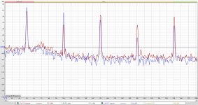
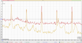
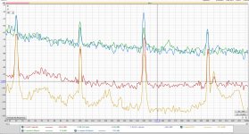
So here a few plots to show what I mean, they compare the RTA in the 'hummy' area. The LH channel is the culprit, and when the system is on mute it is very quiet (and strangely the RH has a slight hum) and then when the system is off mute in operate (play music) mode, the LH channel has what sounds like a quite large increase in hum. Looking at the plots the difference is at 150 Hz, but seems larger than these comparisons suggest. Weird....
Red is LH on operate
Yellow is LH on mute
Green is RH on mute
Blue is RH on operate
Attachments
Last edited:
These are actually from the 211 amp output btw, I will do some more microphone readings later today.
another slightly confusing plot.
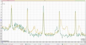
Here I have added microphone in front of LH speaker and in muted has no real audible hum but flicking the switch to operate you can hear a noticeable increase in hum on the LH speaker.
Seems like I am hearing 150 Hz?
Here green is speaker muted, and blue speaker in operate (play)
Here I have added microphone in front of LH speaker and in muted has no real audible hum but flicking the switch to operate you can hear a noticeable increase in hum on the LH speaker.
Seems like I am hearing 150 Hz?
Here green is speaker muted, and blue speaker in operate (play)
Attachments
- Home
- Amplifiers
- Tubes / Valves
- cheap oscilloscope? to help find my damn hummmmm