If the power transformer B+ secondary has a Center Tap, make sure that the center tap goes Directly to the Negative (-) of the First B+ filter cap.
Otherwise, the power transformer replacement has created a Ground Loop, specifically a Hum Ground Loop.
If there is no Center Tap, than be sure to connect the Negative (-) output of the bridge rectifier Directly to the Negative (-) of the First B+ filter cap.
If the B+ uses a Voltage Doubler circuit, I am not sure what can be done.
Even with a mechanically quiet power transformer, there will be hum in the speakers if you have a Hum Ground Loop.
2 separate Hum problems, one is mechanical, one is electrical.
And I am sorry to say, Know Thy Technician/Engineer.
We (and I) all get something that is over our heads from time to time. Solving Hum problems is not easy (just look at the percentage of threads in Tubes/Valves that is about reducing Hum; and look at the average number of Posts/Thread on Hum). I 'rest my case' on that statistic.
Last edited:
Well what I could do that would be more achievable for me and convenient is to use a spare identical transformer I have.... and patch in the leads that are already quite long into the supply points.
I just need a way of confirming the polarity of the new supply and of course retaining the polarity of the old one.
The only thing I have to slightly sheepishly confess is the reason I have 2...well it has a centre tap so it can be wired for 110V and when I got it in a rush tried to measure the output voltages and ran it in the 110v setting with 240v and it errrr.... smoked for a little but.....I turned it off, wired it properly and it seemed to work ok, but I thought at this time 2 things.
1. I should not be trusted to swap this myself.....(hence the £400 repair bill...)
2. I should get a new one just in case....(only cost me about £60 I recall)
hey just a thought.
If you look at the question of polarity on the transformer taps, some of the wires have a black pen mark, suggesting the polarity was checked, some don't. Could a polarity swap in some of the supply taps create a hum?
If you look at the question of polarity on the transformer taps, some of the wires have a black pen mark, suggesting the polarity was checked, some don't. Could a polarity swap in some of the supply taps create a hum?
Attachments
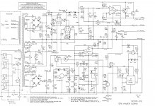
C16 is connected wrong in the schematic (140 V reverse voltage).
The measured voltage was 133 V rather than 140 V DC on the heater of V6 and the humming started after a transformer replacement. If it is a new type of transformer, maybe the voltage is too low and the regulator is out of regulation?
The measured voltage was 133 V rather than 140 V DC on the heater of V6 and the humming started after a transformer replacement. If it is a new type of transformer, maybe the voltage is too low and the regulator is out of regulation?
The cap is in the right way around in the circuit - good to spot that! 🙂
I get 24.06 V on V4 heater and the split at 11.46 on V5 so I think it's working ok?
I get 24.06 V on V4 heater and the split at 11.46 on V5 so I think it's working ok?
Hmm,
V7 heater secondary uses a single 100 Ohm resistor to tie one end to the cathode.
Why did they not use two 100 Ohm (or two 200 Ohm) resistors, and make a Pseudo center tap to connect to V7 cathode?
All the other heater supplies use two resistors, to create Pseudo center taps.
V7 heater secondary uses a single 100 Ohm resistor to tie one end to the cathode.
Why did they not use two 100 Ohm (or two 200 Ohm) resistors, and make a Pseudo center tap to connect to V7 cathode?
All the other heater supplies use two resistors, to create Pseudo center taps.
Last edited:
hey just a thought.
If you look at the question of polarity on the transformer taps, some of the wires have a black pen mark, suggesting the polarity was checked, some don't. Could a polarity swap in some of the supply taps create a hum?
AC doesn't have polarity as such but it does have a phase relationship with other windings and tapping's.
Whether phase matters for minimising hum is an interesting question...
Maybe this question has already been answered, but is the +640 V reasonably close to +640 V?
Well strangely B+1 399-400 and B+2 399-400 on line stage anodes are 180 V4 and 160 V5 , the Cathode on V6 is + 170.
yet AC into HT is actually 394 the HT measures 480 DC, 240 at the split.
V7 runs VERY hot, no sure this is normal?
Hmm,
V7 heater secondary uses a single 100 Ohm resistor to tie one end to the cathode.
Why did they not use two 100 Ohm (or two 200 Ohm) resistors, and make a Pseudo center tap to connect to V7 cathode?
All the other heater supplies use two resistors, to create Pseudo center taps.
Strangely the Mk1 SP8 has two resistors??
oh and one more thing I noticed the Mk I uses 12 ax7 for V8 and my later one Rev E uses 12AT7...strange
found this too https://dalmura.com.au/static/Hum article.pdf
slightly over my knowledge base.....but looks comprehensive
slightly over my knowledge base.....but looks comprehensive
started a new thread as I now have bigger problems...bummer.
Something has gone properly south now
Something has gone properly south now
oh and one more thing I noticed the Mk I uses 12 ax7 for V8 and my later one Rev E uses 12AT7...strange
The 12AX7 has lots of gain and is very sensitive to noise.
On a couple of projects I have abandoned it for a 12AU7.
12AT7 doesn't have quite as much gain as 12AX7 but more than 12AU7.
well strangely now for the 3rd or 4th time that instability of the circuit has gone anbd normal operation returned.....I have done nothing at all but turn it on this morning again and start off with the signal valves out and checking the PS voltages, then introducing the signal valves (turning off in between) and now it's working again.
My only thoughts for the instability are:
1. my mains voltage sometimes dropping (no idea if it does this)
2. the optocouplers now out of circuit causing some sort of occasional instability
3. C24 as advised by audiowize somehow partly way on it's way out
Any idea how to trace an intermittent fault, or is that like impossible.
When it was faulty the voltages I would normally be able to track around the circuit were completely unstable?
I am a bit lost on this one!
Well, to prove or disprove point number 1 (mains voltage) you can plug it into a variac and switch the Amp on under both 7% under and 7% over line voltages. To see what happens. But tube amps shouldn't be so sensitive To the typical homes line variations in the first place, A 7% error test is beyond anything your home is experiencing.
Last edited:
so back on topic, I might have found the cheapest Oscilloscope possible 🙂 £17
It's an existing MacBook, a Behringer audio interface
Behringer U-Control UCA202 – Thomann UK
and a home made cable 🙂
I used the oscilloscope function to measure the outer foil of capacitors for directional installation, I have used the signal generator and oscilloscope to check phase of my amplifier, and now I want to use it to find the source of a small hum in 1 channel of my pre-amp.
(of course with a microphone you can measure speakers too)
BUT I need some thinking advice so I don't melt it 🙂
I want to measure the signal coming from various stages of my preamp, and some of these have high DC voltages, so should I put a large resistor or perhaps a capacitor in line with the signal on the probe.??
This will then feed the audio interface into the laptop and show me the signal with an RTA.
What do you think, and has anyone else used this cheap and so far very effective solution 🙂
It all depends on the input impedance and input sensitivity of the do-dah you feed the signal into meaning you will have to scale parts to suit.
Use a DC blocking cap such as a film cap of 400v rating. Series resistor of wattage to withstand the expected full voltage encountered. Use back to back Zener and diode network directly across the input of the do-dah as voltage clamp to prevent excess voltage making its way in. I would guess something like protection clamping at -/+5 volts would be OK.
Its not a great way of doing things tbh... proper scope is infinitely better 🙂
- Home
- Amplifiers
- Tubes / Valves
- cheap oscilloscope? to help find my damn hummmmm