Yes, its a good one. I once had one , it's still alive at a friend. Recommended!ok - so maybe a punt on an old scope makes some sense ....£50 or so.
what spec (do I need what Mhz?), and there are lots of tektronics on ebay, is that the brand to go for - or is that irrelevant.
I guess I want probes etc with it or that will add up?
Thanks
Yep. Those "breadbox" scopes are pretty decent. Personally, I'd go for a newer model with colour screen, but I've used those TDS1002 quite a bit. They're good scopes.
Tom
Yes, Tektronix is THE brand to go for. Most decent scopes will be 60 or 100Mhz. You don't need that, 20 would do but a 20 meg scope will be a POS.
For a bit more money, you can get one of the new color screen LCD scopes, but their resolution is done differently, as it is not a resistor, but a digital scaling. I have been told, the very newest Teks are not as good as the 1000 series. Another feature you can get is storage. I was looking at a new scope, as not much more because I was working on a power up/down delay that was not behaving as I ( or Spice) expected and I needed a single shot storage.
Aligent/ HP are a bit different. Good, but never cared for them. For new inexpensive, I have been advised Rigol is more reliable than Hantek. For about $300 you can get a new Rigol 100 meg storage scope. At least here in the US. That is what I was about to do , but solved the problem another way.
By the time I bid on a 100 series Tek, with shipping it was only $100 less than a new one. I don't pay more than half retail for used equipment. Watch out as I have seen bids in excess of new! Not by now, people actually bid over retail for available stuff.
These cheap 2-pack probes are fine for the hobbyist
an example, many vendors: 2 Pack P6100 100 MHz Oscilloscope Probe 10:1 and 1:1 Switchable for Rigol A W6C8 | eBay
Don't know the resolution of your multimeter but a good 5 digit bench should be sensitive enough for anything.
Tektronix scopes
HP logic analyzers
Fluke meters
Lambda supplies
Wavetek generators.
Gen-Rad bridges
This is what we use in the real world when yo need to make a living.
I use a £6 multimeter off ebay !
And remarkably it does the job.
I am a clumsy idiot so always dropping stuff or splattering it with soldler so cheap and easy replaceable is good.
My 20MHz scope was second hand off ebay for £45 with dodgy second channel which I rarely use.
Sig gen was ebay too, about £35 and had scope and sig gen for about 10 years now with no problems.
I did have a Phillips scope but it didnt last long, crammed full of electronics, too much to go wrong. Much prefer my simple Hitachi scope.
Some of my work now is digital scope design and thats pushing the 20MHz scope past its limits.
Will this one be suitable? Any reason it would not be suitable? I'm thinking about buying one. Mostly for SS Pre and power amp testing and checking after build.
https://www.newark.com/multicomp-pr...scilloscope-20mhz/dp/10AH2392?ost=mp720009+us
https://www.newark.com/multicomp-pr...scilloscope-20mhz/dp/10AH2392?ost=mp720009+us
1000V CATIII multimeter is available at most home DIY stores/electric stores. Check the probes too but they’re cheap.
Don't skimp on bandwidth. I've had a 6DJ8 circuit oscillate into the VHF range.
I have similar experience with transistor circuits. I used to have a 20 MHz analogue scope and later bought a 150 MHz analogue scope. With discrete circuits consisting of BC547 and similar transistors, wire-parasitic-related oscillations were completely invisible on the 20 MHz scope. You could only see indirect effects, like weird bias points, hand effect and in one case a loud hum that made no sense at all.
With the 150 MHz scope, I simply see the oscillations, even when they are a bit above 150 MHz (the displayed waveform and amplitude are then wrong, but you still see something up to 300 MHz or so).
Will this one be suitable? Any reason it would not be suitable? I'm thinking about buying one. Mostly for SS Pre and power amp testing and checking after build.
https://www.newark.com/multicomp-pr...scilloscope-20mhz/dp/10AH2392?ost=mp720009+us
You're much better off with the 100Mhz models. Fast opamps have no problems oscillating at high frequencies. I had an LM6171 oscillating near 100Mhz on a breadboard!
1. Unfortunately, sometimes those 100MHz oscillations go away when you probe the circuit with a 10pF 10 Meg Ohm 10X scope probe.
No one test equipment selection works for every situation.
2. Another situation:
Because I work on tube amps, I did purchase a Tek P5100 2.5kV probe. It divides the voltage by 100. It has a 9 Meg series resistor at the tip, but more importantly a 110k resistor at the BNC end. It connects across the hot and ground inside that probe box. It will not break those scope inputs that are set to AC Coupling.
Those scope inputs are only rated for 300VDC (even when AC coupled), so a common 10x probe with only a 9 Meg series resistor, will send the DC to the coupling cap, and from the coupling cap to the scope 1Meg resistor input to ground. With the 10X probe, and voltages larger than 300VDC + Peak Voltage, you risk shorting the AC coupling cap, and also risk blowing out the rest of the input circuit as well.
The P5100 probe as expensive as it is, is no more expensive than repairing or than replacing many scopes.
And while your scope is in for repair, or you are waiting for a replacement, you can not test your latest tube amplifier.
Last edited:
I typically use the ground lead of a 1:1 probe as a loop antenna to find oscillations.
Good point about the 10:1 probes and AC coupling capacitors!
Good point about the 10:1 probes and AC coupling capacitors!
MarcelvdG,
The loop is a good idea!
Some others will simply cover the probe tip with shrink tubing, and bring the tip right up to the circuit under test, even forming a low pF cap as the dielectric of the shrink tubing contacts the circuit.
I have been fortunate so far with just a 25MHz digital scope (love the FFT function).
The solid state devices I use in tube amps so far are confined to the following:
B+ rectifiers (I prefer choke input when possible, otherwise no more than 4uF first cap).
IXYS 900V part, and always use a gate stopper.
LM371
LM334
One thing about solid state oscillation:
Often it will only occur during a particular voltage during the positive or negative alternation of the tube's voltage swing (like a 5, 15, or 30 degree portion of a sine wave).
Things like fT are variable, depending on the voltage and current.
So, at some point, the circuits parasitic L and parasitic C make a resonator that is at the frequency that is just right for the 'fT' at that combination of voltage and current.
Bipolar transistors have been made to oscillate at up to about 1.2x fT.
I am not well versed on the oscillation frequency limits of MOSFETs, but they must be somewhat similar in nature.
MOSFETs exhibit very large capacitance changes versus large voltage swings.
I am retired now, so I do not have access to the $50,000 10Hz to 4 GHz Vector Network Analyzer (VNA), and no access to the 6GHz Real Time Spectrum Analyzer, 325GHz waveguide mixers and spectrum analyzer with 18GHz Local Oscillator, etc.
With the VNA, I did impedance/phase plots of loudspeakers, gain/phase of tube amplifiers, and gain/phase of tube amplifiers when they were driving real loudspeaker loads.
Then there was interstage transformer gain/phase/impedance measurements, and output transformer gain/phase/impedance measurements. And for transformers, I measured Inductance, Distributed capacitance, and Leakage Inductance too.
Then there was the testing of speaker cables, throughput with the output open, output shorted (no throughput), output terminated with 8 Ohms, and insertion loss with 8 Ohm termination too. Then the impedance of the speaker cable was measured with the output open, shorted, and terminated with 8 Ohms.
Those days at work after hours, was a great time for measurements.
Last edited:
Given the OP is initially concerned about a valve amp, and fault finding hum, I recommend the initial effort is best served by using a USB soundcard type interface like a focusrite, that allows 192kHz sampling, and REW software on a reasonably new laptop.
Hum faultfinding in a valve amp does not require HV dc probing, and at most about 100-200Vdc level. If the thought is that a higher level of Vdc probing is needed, then I recommend some more learning curve is needed.
Such a soundcard and 10:1 probe will have a far lower noise floor than any scope, and the software also provides time domain scope view of waveform for confidence building, even though a frequency spectrum is the main tool to use.
Such a measurement system has no mains ground loop noise due to the laptop, which can easily be the bane of connecting any mains power instrument to an amp for hum investigation.
This type of tool is quite mature now, with many many forum threads by those who have gone that path. There is no need for any form of signal amplifier in this setup, as the soundcard interface's noise floor is well below the noise floor of any valve amp, allowing any mains related or other quirky resonance signal to be seen poking up out of the floor. There is no initial need for dual probing for this type of faultfinding.
This type of measurement setup also allows a pretty full-on characterisation of a valve amp, including distortions, noise levels, stability performance, and frequency responses, which would keep any valve amp tinkerer absorbed for months.
Yes there are quite detailed technical issues that benefit from lower and higher bandwidth measurement - which a scope or wideband voltmeter would be needed to assess, but those issues are not typically mainstream for a first in assessment, and I suggest are initially beyond the pay-grade of the OP, and better left to later.
Some sound cards may not deal well with a 10:1 probe, a blocking capacitor, and probing
onto 90V of a 6DJ8 plate.
During the time when the cap starts to charge, the sound card can receive a transient
(the cap is a 'dead short' from 90V in that case, when the probe is first connected).
After the cap is charged to 90V, then often the probe is placed on the self biased cathode of the same circuit (so the 90V from the cap has to go somewhere, right into the soundcard).
You are right . . .
A 100x probe and a scope will not solve the original posters problem.
My writeup about the 100X probe was as in informational for those who do not know.
But probing around with a sound card might just create another problem for the original poster, unless he knows about the charge and discharge of a coupling cap.
However, I see that after 52 posts, nobody has been able to solve the original poster's problem.
Most of my amplifiers have less than 100uV hum at the 4 and/or 8 Ohm output tap.
Without being there at the original poster's site, I am probably not going to solve his problem.
Come on posters, solve the original poster's problem, or I am likely to add more stories to this thread.
And while we are discussing the original poster's problem, Did I miss a post or two?
I have not seen a mention of the model of the preamp that is being tested.
I have not see a schematic of the model of the preamp that is being tested.
I have not seen a picture of the preamp that is being tested.
That is not the fault of the posters who try and help the original poster out.
We all tend to get carried away with what test equipment works for us (but very importantly, on the preamps and amplifiers that We have).
As far as I can see, this thread is not about solving for the OP's supposed problem, as the thread is about a tool the OP can use, and the OP has provided no information what so ever about his 'problem', and I'd suggest even if the OP started to describe his actual preamp then we would circle back to what tools are available to progress the issue (apart from tube swapping).
The aim with a soundcard system is to identify one which can support a 10:1 with a known input resistance (not just impedance). The venerable EMU 0404 etc have a 1Meg input resistance to act nicely with a 100:1 probe. I can't guarantee the Focusrite Scarlet's have an input 1.5Meg resistance, but the specs indicate it does and there are now many owners who could confirm. The 1.5M is not a concern with a probe meant for 1Meg, as a multimeter is always needed for absolute measurements, and the frequency response is usually auto-calibrated for a flat response as part of the setup.
Probing an anode voltage (or even cathodyne cathode voltage) directly is almost never a requirement, as there is typically a coupling cap or coupling transformer after the anode to probe for signal at ground level.
There is always the risk of accidently connecting a probe to a HV node, and hopefully any newcomer takes the time to identify hazardous nodes, and even double check node DCV with a multimeter before de-energising and reconnecting with a probe, and then re-energising.
Last edited:
trobbins,
I agree absolutely.
This thread is about test equipment to trace the cause of hum in a preamp.
A moving coil preamp?
A moving magnet preamp?
A line level preamp?
Knowing that might just help to define what test equipment is required to do the testing.
I agree absolutely.
This thread is about test equipment to trace the cause of hum in a preamp.
A moving coil preamp?
A moving magnet preamp?
A line level preamp?
Knowing that might just help to define what test equipment is required to do the testing.
sounds err.. uber complicated to a newbie.
I am an engineer, I have used scope's 20 years ago but that sort of is in my distant memory banks, not readily accessible !
All I want is to help find my source of hum, and the scope is a tool to help.
Suppose I have one, then how do I use it as an investigatory tool.....even before I work out who to use the tool as a piece of equipment, assuming it works to provide a result with the tight probe/protection/settings etc 🙂
Sorry to be so err.....dumb
Remember the scope is simply a voltmeter that plots voltage against time.
A traditional scope with a 10:1 divider probe is essentially safe on most equipment. Just check the probes maximum voltage rating to be sure but many are around 400vdc or more from memory.
If you are looking at points with no or low DC volts then you can switch the probe to 1:1 to gain the extra sensitivity. Old scopes are tough and it takes serious abuse to actually damage. Three or four hundreds volts DC isn't go to do it...
No hum = flat trace. The problems come when troubleshooting really low levels of hum and in these cases you need good practice with test equipment grounding and so on.
You can always isolate stages in a typically valve preamp. Have just the output buffer working for example and disconnect the signal from its input, grounding via a cap if necessary to see where the hum begins to enter the chain.
Look at the frequency and nature of the hum voltage as that tells you where it originates.
You have a system that is giving you hum problems. Right?
It might be the preamp.
Perhaps you have already proved that the preamp is the problem.
A low level signal, goes to a high gain preamp, that connects to a high gain power amp,
that connects to very efficient horn loaded loudspeakers.
You hear some hum.
A low level signal, goes to a low gain preamp, that connects to a low gain power amp,
that connects to in-efficient speaker systems.
You hear some hum.
The causes of the hum in those two systems may be completely different, or may be the same.
And the preamp in both systems may, or may not, be causing the problem.
If you have a system, no music playing, and you do not hear any hum; and then you add a preamp in the middle and now you hear hum, that does not prove that it is the preamp (example, the preamp adds gain, and now you can hear the hum that was already in the signal source that is not yet playing music).
Part of troubleshooting hum in a system requires doing some things to prove that the preamp is, or is not, the main problem.
Sometimes the hum is merely the interaction of a signal source, a preamp, and a power amp, and even though they are on the same power strip, they have a ground loop that is causing the hum.
How did you determine that your preamp has hum?
If hum output from a preamp is at a very high level; even an inexpensive DMM, VOM, or inexpensive scope and 1x or even 10x probe may be able to measure it (but may not be able to troubleshoot the cause of the hum in the earlier stage or input circuitry of the preamp).
Yes, then a sound card may be needed.
We are at Post # 59, and we know nothing about your system, nothing about your preamp, nothing about the "sound" / "timbre" of the hum.
Knowing something about your system, and the level of the hum might help to be able to select appropriate test equipment.
Last edited:
This thread is split off from another thread called "Potentiometer sound quality"
The culprit is an ARC SP8 later generation with 6DJ8 instead of 12AX7 in the phono stage. 2 techs have already messed with it, including a replacement of the power transformer. Big $$$ from the OP for no result.

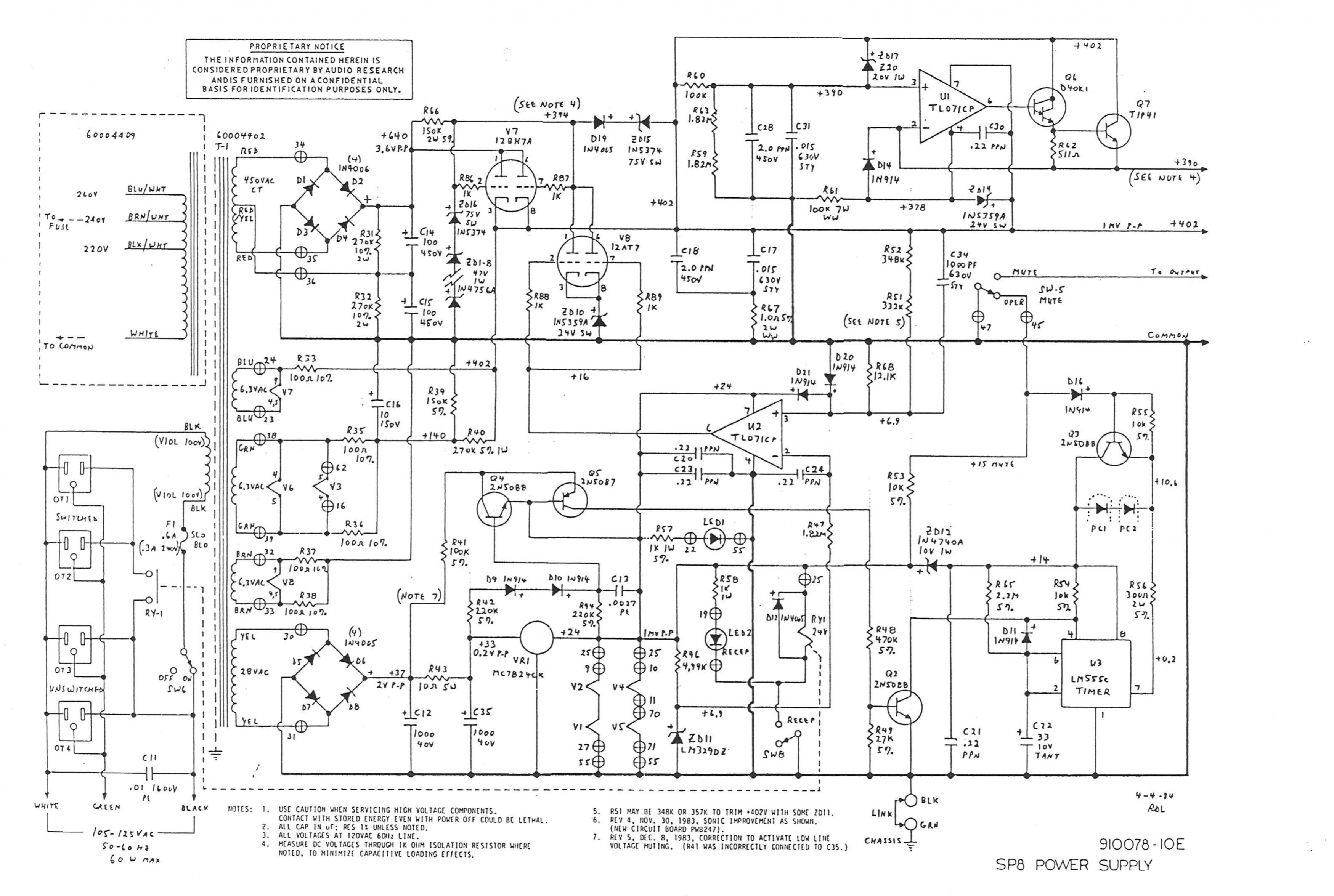
To stay on topic, I have both an analog scope (Tek 2236, $100 on eBay) and a Focusrite Solo. They serve different purpose.
The culprit is an ARC SP8 later generation with 6DJ8 instead of 12AX7 in the phono stage. 2 techs have already messed with it, including a replacement of the power transformer. Big $$$ from the OP for no result.
To stay on topic, I have both an analog scope (Tek 2236, $100 on eBay) and a Focusrite Solo. They serve different purpose.
- Home
- Amplifiers
- Tubes / Valves
- cheap oscilloscope? to help find my damn hummmmm