Zung,
I am understandably confused.
Are you working with the original poster of this thread?
Does he have that preamp model?
Are you just using that preamp model as an example of what test equipment is needed for the different parts of the circuit, and different signal levels?
Is this split of the threads just for the same exact preamp, not just the model, but the same serial number?
In the original thread, I tried to help the OP with the usual tricks, and they don't work. So I told him to get a scope: without it, we're blind. I think the OP created this thread because of the different topic.
So do we use this thread to continue the saga, or return to that other thread that has taken 60 posts to identify in this thread?
Is there a summary of the problem and fault-finding to date, including what has been heard/measured, and what has been removed from the assessment and how, or do we read through the 59 posts in the other thread?
Is there a summary of the problem and fault-finding to date, including what has been heard/measured, and what has been removed from the assessment and how, or do we read through the 59 posts in the other thread?
And while we are discussing the original poster's problem, Did I miss a post or two?
I have not seen a mention of the model of the preamp that is being tested.
I have not see a schematic of the model of the preamp that is being tested.
I have not seen a picture of the preamp that is being tested.
That is not the fault of the posters who try and help the original poster out.
We all tend to get carried away with what test equipment works for us (but very importantly, on the preamps and amplifiers that We have).
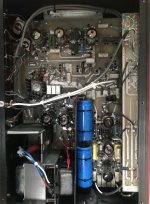
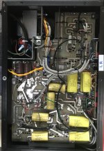
It's an ARC SP8 Rev E.
https://www.arcdb.ws/Database/SP8/ARC_SP8_manual.pdf
So far I have added metal shields around the mains transformer in the places where it audibly improved.
I have added shielding around heater and AC cables.
I have changed PS caps in HT and LT
apart from the PS caps they all improved things a bit, its acceptable now but still there. Hence the scope as next steps.
If I got rid of the hum I would not actually need a scope!!
Attachments
So do we use this thread to continue the saga, or return to that other thread that has taken 60 posts to identify in this thread?
Is there a summary of the problem and fault-finding to date, including what has been heard/measured, and what has been removed from the assessment and how, or do we read through the 59 posts in the other thread?
Sorry for confusion, and filling up everyones inbox this thread was about getting an oscilloscope as recommended from the other thread!!
OK, then it seems reasonable to defer questions about the hum issue itself to the other thread. Although without a summary of what has been measured, and with what, I don't see any compelling reason offered to buy any more tools.
I have measured circuit voltages DC where possible and AC from the transformer, and they are all close to the specified levels, is it useful to list these for reference?
thanks for all the help so far 🙂
thanks for all the help so far 🙂
Fault finding always begins with checking supply voltages so it is good you have done that.
As to the hum...
1/ Is it affected by the volume control?
2/ If yes to the above, then does the input selector setting make any difference (excluding the phono input)?
As to the hum...
1/ Is it affected by the volume control?
2/ If yes to the above, then does the input selector setting make any difference (excluding the phono input)?
Mooly,
Now you are getting us to focus on the Symptoms.
We may get somewhere now.
Those are good questions.
I will ask one more question:
What is the maximum hum level out of the preamp?
(under the worst case settings).
That might be measurable by a DMM (my handhold DMM reads down to 100uV AC).
From there, we may be able to determine if a scope and 1x probe (plus a special accessory) or a soundcard (plus a special accessory) are needed to measure the lower level hum in the earlier stages.
Scope 10X probes attenuate too much. 1x probes and medium to high voltages require a
"special accessory" box (a high voltage coupling cap, and a shorting switch). The probe connects to the box input BNC.
The output BNC connects to the scope (or sound card).
The coupling cap connects from the box input to the box output.
A toggle switch in the box shorts the output (and is opened After the cap is charged).
The key to proper operation is this:
The switch is set to short.
The 1x probe is connected to any point in the preamp (any preamp DC voltage is OK).
The capacitor charges up (almost instantly).
The switch is set to open.
Measure the hum.
Then, before moving the probe to another point, short the switch.
Careful, the probe has DC voltage on it (it is charged).
And if you touch the 1X probe tip, be prepared to be shocked.
So when you remove the probe, and short the switch, connect the probe to ground first and discharge the voltage that is already on the cap.
Oh, you should have a 1k Ohm resistor in the special box, in series with the cap, that will prevent you from "welding" the 1X probe tip when you discharge the cap.
Now, you can connect the probe to a Grid (the cap has been discharged, so it will not "kick" at the grid).
Then open the shorting switch again, and measure the hum on the grid.
This method can be dangerous to a scope input, or to a sound-card, Unless . . .
You always remember the order of setup, and the proper times and proper order to charge and the proper times and order to discharge the coupling cap.
Make sure the coupling cap is 600V rated or more (no electrolytic caps, leakage is a major issue for this application). That will work for preamplifier voltages.
A 0.1uF cap is 80k Ohms of capacitive reactance at 20Hz, and 26.5k Ohms at 60Hz.
That works for a 1 Meg Ohm scope input.
I do not know what the rated input resistance/impedance is for sound-cards,
but a 25k input impedance will cause the hum you measure to be -3dB below its actual amplitude.
I am sorry for the very complex explanation, but it is the best method for most scopes and for some sound-cards.
protect the test equipment.
Suppose you are on a US Naval Destroyer in the Gulf of Tonkin.
The Captain of the ship is "breathing down your neck" to fix an important piece of electronic gear, you have to invent test methods and troubleshooting methods that they did not teach in 9 months of 8 hour a day technician training.
Well, I lied about the Captain "breathing down your neck", but it is just as bad when it comes down from the chain of command.
Last edited:
It is good to have the DC voltages at the proper operating levels.
+/- 10% is normal, sometimes +/- 20% is OK, especially for non regulated supplies, and Power Mains that are perhaps 5% from the manufacturers power mains voltage.
With DC voltages correct (and usually the currents are correct then too), that does not prevent Hum . . .
Internal Preamp Ground Loop Hum, Wiring Placement caused Hum, Un-bypassed Cathode Filament to Cathode Leakage Hum, etc.
And then there is Hum that is caused by Turntable wiring, Magnetic Cartridge pickup of other magnetic fields; other signal sources that are plugged into the power mains, and ground loops with the preamp caused by that; and power amplifiers that also cause ground loops with the preamp.
And do not forget the ground loops that are caused by the interaction of Computers, sound-cards, and Scopes.
Most of those use switching supplies (I can often see not only 60Hz, 120Hz, but switcher high frequency ground loops).
It is merely conservation of energy, and the fact that every ground wire is both a Resistor and an Inductor.
Current through a resistor in series with an inductor will create a voltage drop, no matter how small (amplify that, and you have a problem).
Computers, Scopes, etc., (and Audio Gear might have to) have to meet International regulations for EMI (Electro Magnetic Interference).
The problem is, take two pieces of gear, and "marry them". They Individually meet the EMI specs, but are not compatible with each other.
That raises the issue of EMC (Electro Magnetic Compatibility, which is an Oxymoron [not compatible]).
I can see the Computer Switcher EMI when I connect the computer earphone output to a tube power amp (the computer switcher EMI interference appears at the output of the tube amp).
I can see the scope Switcher EMI when I connect a scope to a tube power amp (the scope switcher EMI interference appears at the output of the tube amp).
Ground Loops Happen!
If you look under the Rug, you will find some dirt.
We still do need that scope or sound-card, and special accessory box.
Good luck troubleshooting the preamp.
Last edited:
Fault finding always begins with checking supply voltages so it is good you have done that.
As to the hum...
1/ Is it affected by the volume control?
Well it is there at zero volume in the background (now low level after all the shielding). Turn the volume up and it comes in towards the maximum.
2/ If yes to the above, then does the input selector setting make any difference (excluding the phono input)?
yes, but not as you might think, I play my DAC through the tuner input and this is the lowest with a DAC connected, and then the other inputs are worse (louder)
Just put a frequency app on it and it's 50HZ through the speakers
1000V CATIII multimeter is available at most home DIY stores/electric stores. Check the probes too but they’re cheap.
I don't see the attraction of cheap multimeters. A calibrated Fluke 70-series or 80-series can be had for not that much on the used market. I've used my Fluke 73 since the early 90s when I got it. I added a pair of HP 34401A bench top meters some ten years ago.
The cheap meters are often worthless for debugging audio circuits because they can't measure above 400 Hz and often don't resolve better than 0.1-1 V on the AC setting. That's useless for line-level work.
Tom
So you begin with just the preamp and its power amp connected up and a pair of speakers. Fit shorting plugs to the inputs under test (go through them all) and see if there is any background hum and whether or not the volume affects it. Have nothing else connected to the preamp.
Inputs that float can be noisy, hence the shorting plugs.
50 Hz hum sounds like either a ground loop or a radiated field (such as from a transformer) being picked up.
The power supply with its full wave rectifiers would produce 100Hz rather than 50Hz if for example the noise was caused by ripple on the rails.
Mooly,
Good job narrowing in, by checking symptoms.
You would be welcome on the US Naval Destroyer I was on (well, I am not the US or UK governments, but I would have welcomed you ).
Good job narrowing in, by checking symptoms.
You would be welcome on the US Naval Destroyer I was on (well, I am not the US or UK governments, but I would have welcomed you ).
Lol, thanks 🙂
Fault finding is always about being both logical and also collecting as much evidence as you can in a non destructive way, and with as little physical intervention as is possible.
Fault finding is always about being both logical and also collecting as much evidence as you can in a non destructive way, and with as little physical intervention as is possible.
yes, but not as you might think, I play my DAC through the tuner input and this is the lowest with a DAC connected, and then the other inputs are worse (louder)
Sounds like a hum current getting injected into the inputs, rather than a hum voltage or hum injected somewhere further down the chain. Mooly's shorting plug experiment is the indeed the next logical step.
The idea that a scope will help find a hum that is less that overpowering is deeply flawed. Most scopes are based on unbalanced common ground inputs which is exactly the reason that most problems like "hum" occur. I suggest you use your ears and the schematic along with some capacitors. If the hum is not normal for the amp then it's probably a dried up electrolytic and shunting suspect power supply caps will find it. If this is a tube amp then you could have a cathode shorted to the heater circuit. Removing and replacing or moving tubes around should find it. Shorting the signal path tells you if the noise originated before or after that point. If that point has B+ on it then you have to use a capacitor. The good thing about tubes is that it's hard to damage them. Be careful.
PS. If it only hums with inputs connected then you have a "ground loop", ie the safety ground of the amp and signal source hare not exactly zero volts so a current flows between the amp and DAC (etc) ground. The solution is to be sure they are grounded (powered) from the same place. Some times you can lift one safety ground but then you have a safety problem.
PS. If it only hums with inputs connected then you have a "ground loop", ie the safety ground of the amp and signal source hare not exactly zero volts so a current flows between the amp and DAC (etc) ground. The solution is to be sure they are grounded (powered) from the same place. Some times you can lift one safety ground but then you have a safety problem.
Last edited:
So you begin with just the preamp and its power amp connected up and a pair of speakers. Fit shorting plugs to the inputs under test (go through them all) and see if there is any background hum and whether or not the volume affects it. Have nothing else connected to the preamp.
Inputs that float can be noisy, hence the shorting plugs.
50 Hz hum sounds like either a ground loop or a radiated field (such as from a transformer) being picked up.
The power supply with its full wave rectifiers would produce 100Hz rather than 50Hz if for example the noise was caused by ripple on the rails.
So I have had a replacement mains transformer fitted.....so this could be creating a larger than desirable field. This would explain all the benefit of shielding I have had. What is the best way to shield the transformer effectively. Steel / Copper ?
So I have had a replacement mains transformer fitted.....so this could be creating a larger than desirable field. This would explain all the benefit of shielding I have had. What is the best way to shield the transformer effectively. Steel / Copper ?
Electric coupling: any grounded plate that conducts reasonably well can shield electric fields, so any kind of metal foil can do the trick, provided you can reliably ground it. Copper foil and steel will work well, aluminium may be problematic because of the need to ground it reliably.
Magnetic coupling: low-frequency magnetic fields can only be shielded by a shield with a high permeability or a thickness several times greater than the skin depth, which decreases with increasing permeability (see Skin effect - Wikipedia ). For 50 Hz, that means a copper layer of several centimetres thick or a steel layer of several millimetres thick. Mu-metal is an alloy meant specifically for low-frequency magnetic shielding, see Mu-metal - Wikipedia
I think it is best to first see what comes out of Mooly's shorting plug experiment.
- Home
- Amplifiers
- Tubes / Valves
- cheap oscilloscope? to help find my damn hummmmm